 Ricardo Sappia
Introduction
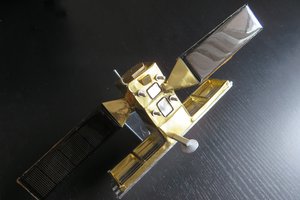
In the following steps it is described how I created this sculpture. The intention of this description is to show the steps and give some ideas about how to make this kind of solar circuit sculptures.
Build steps
Template and forms
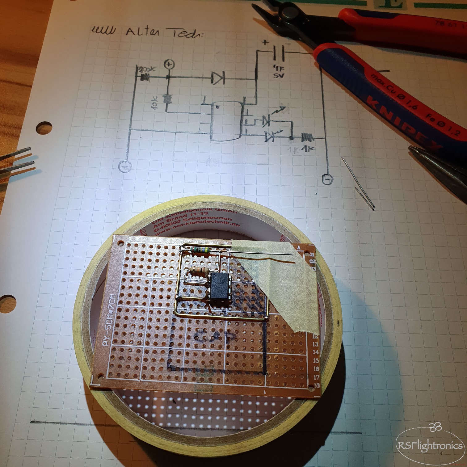
The first step is to define what form our sculpture will have. In this case, I already had an idea of the satellite form factor I wanted so I proceed to draw it on paper so it can be used as template when building the frame.
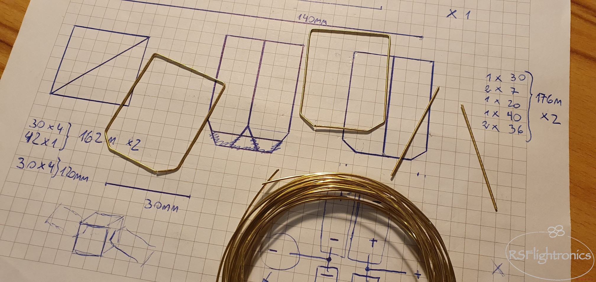
It is important to know already the dimension of the solar panels so it helps us to have an idea of the needed sizes.
Once the form is defined, the brass rod can be cut. For that, the template is our friend :)
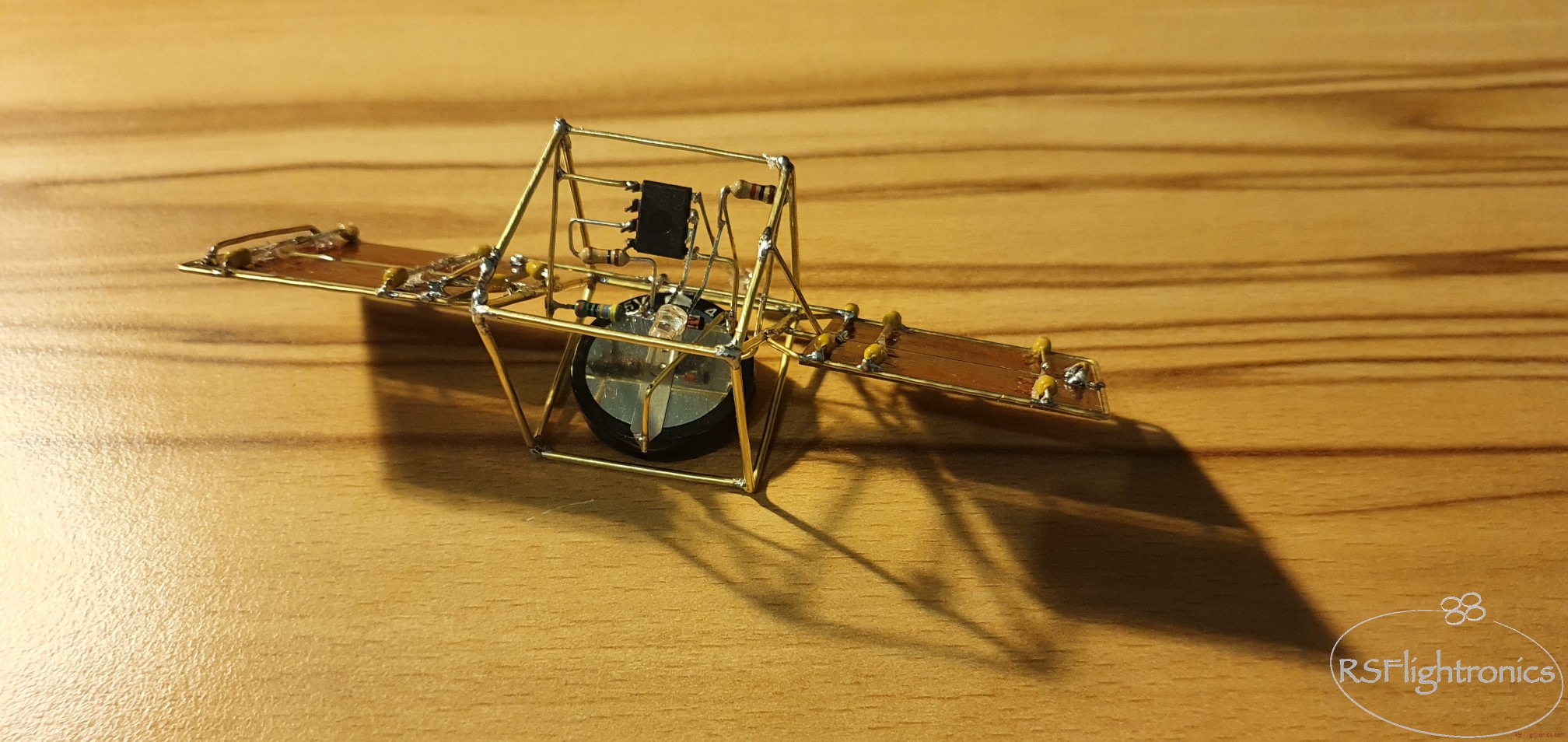
For the main structure I used a 0,8mm brass rod. This diameter brings already very good stability to the sculpture and for the inner guts it can be used a thinner brass rod, in this case a 0,6mm will do it.
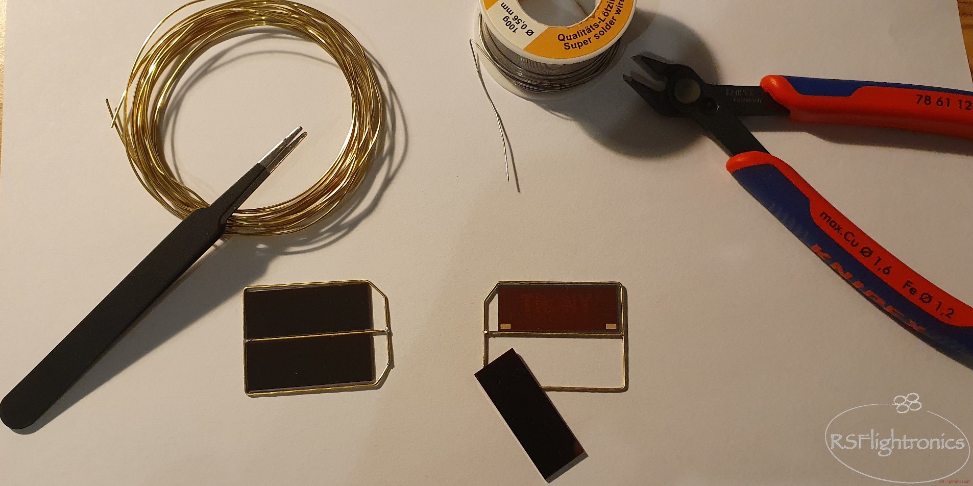
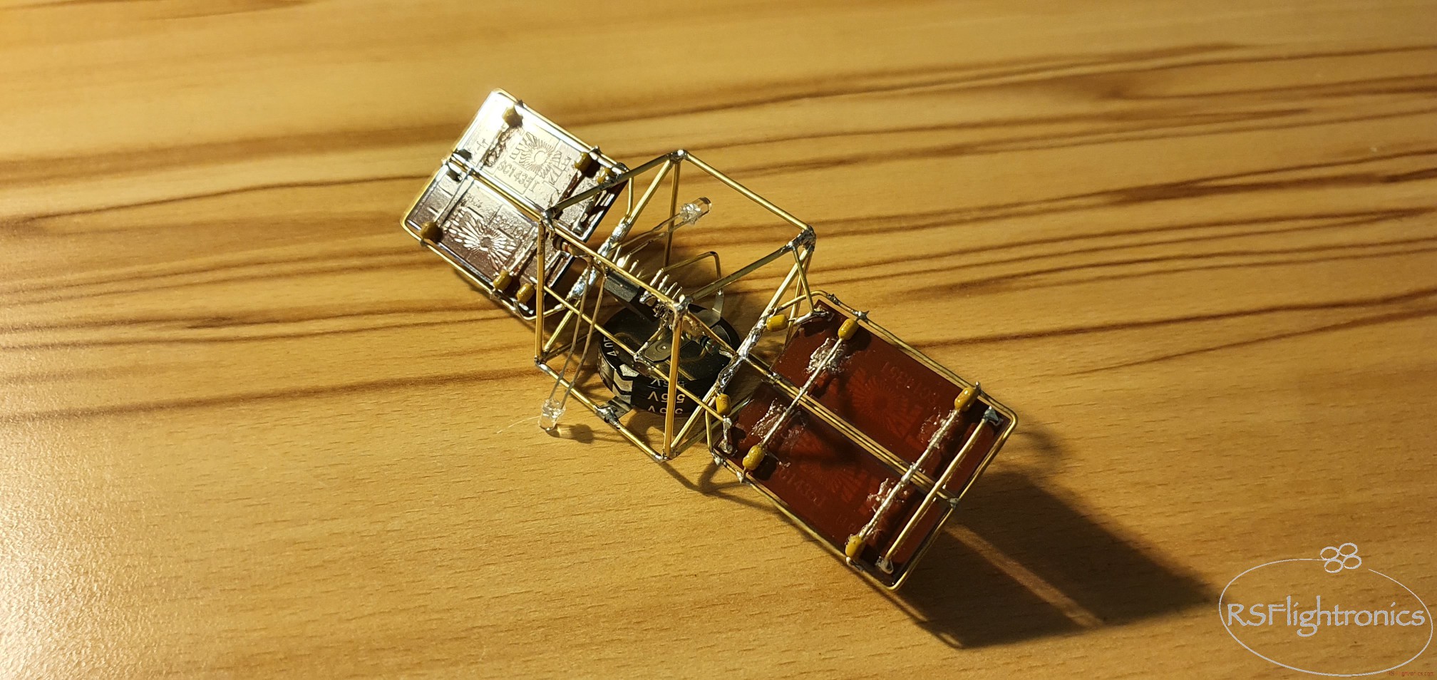
When soldering the solar cells, I learnt that high soldering temperatures must be avoided. Don´t go over 300°C or the conducting pad will be wasted... It costed me about three solar cells to learn that...
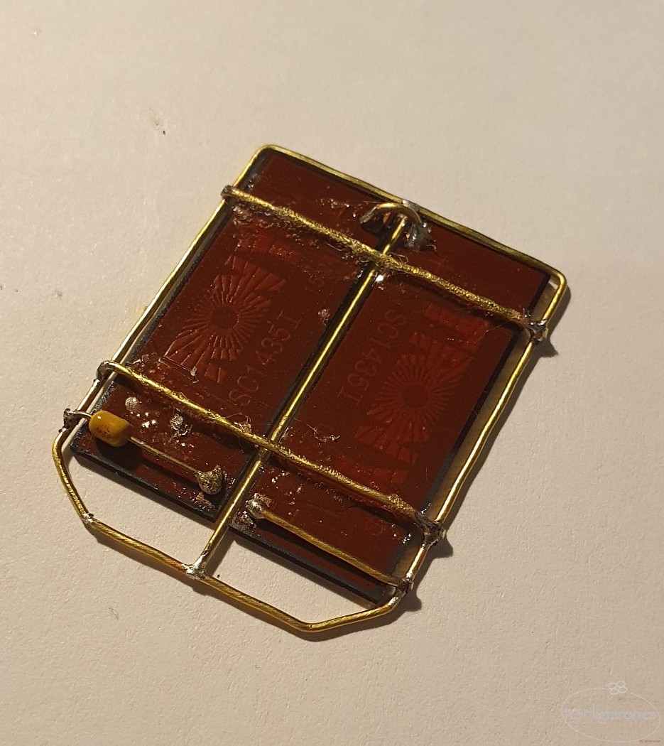
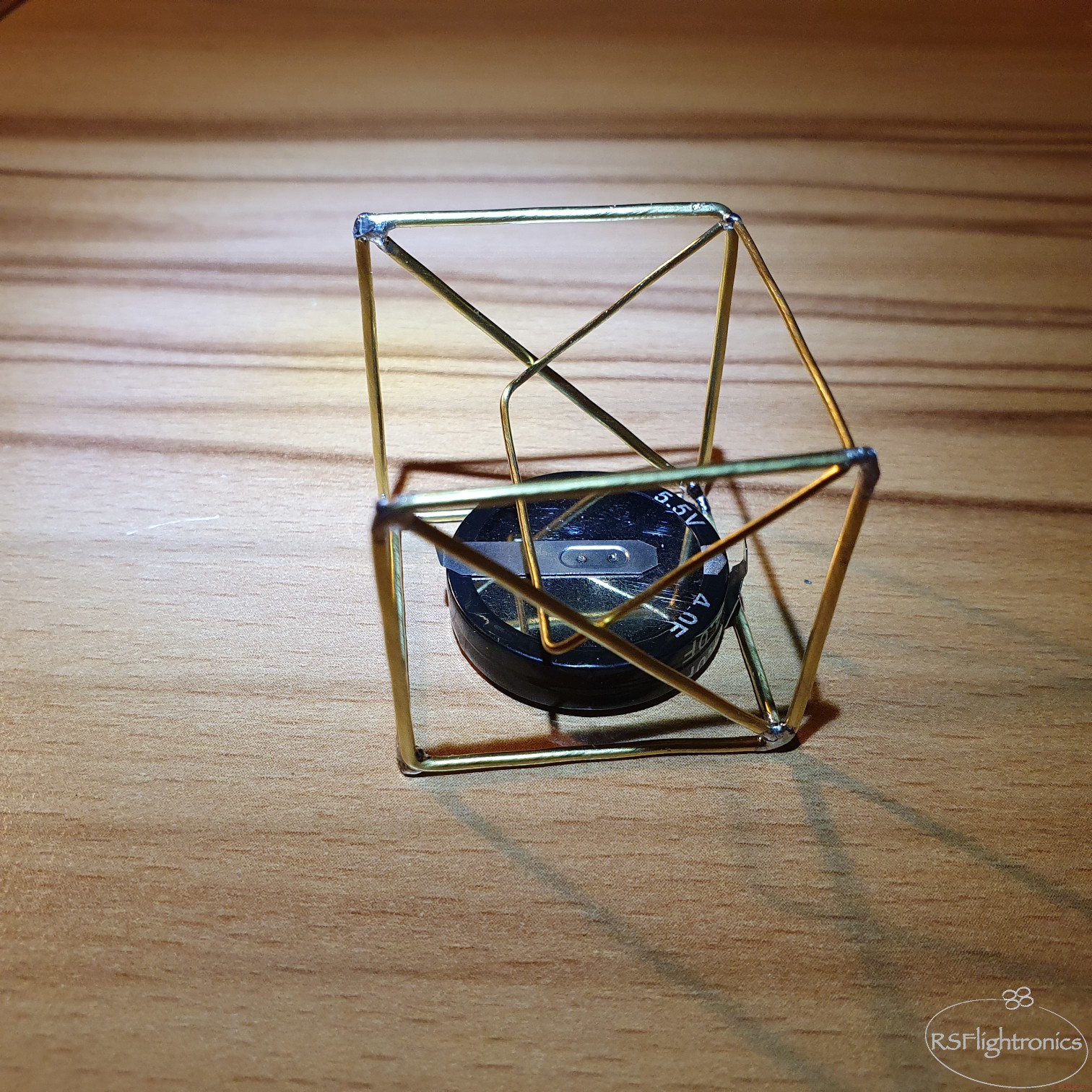
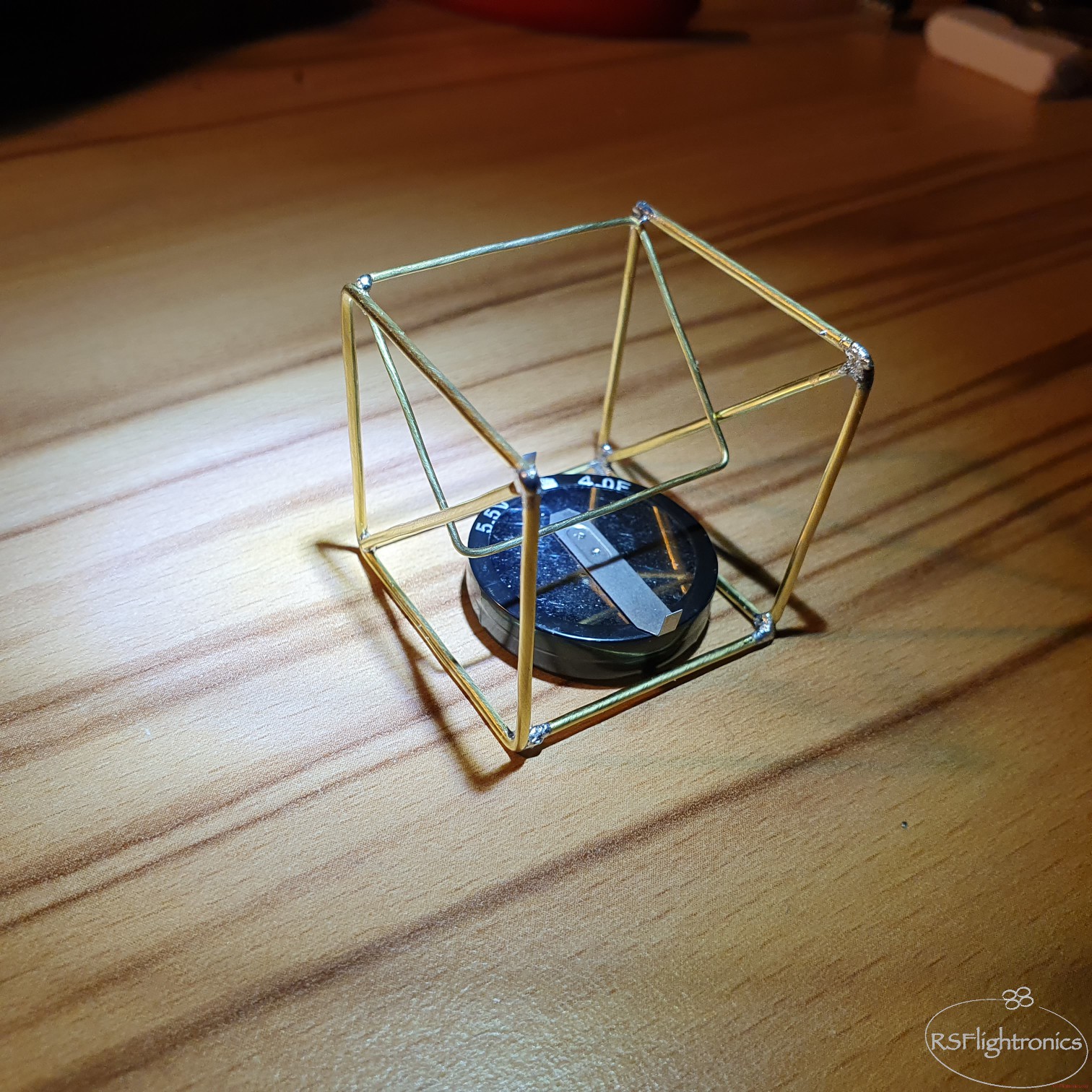
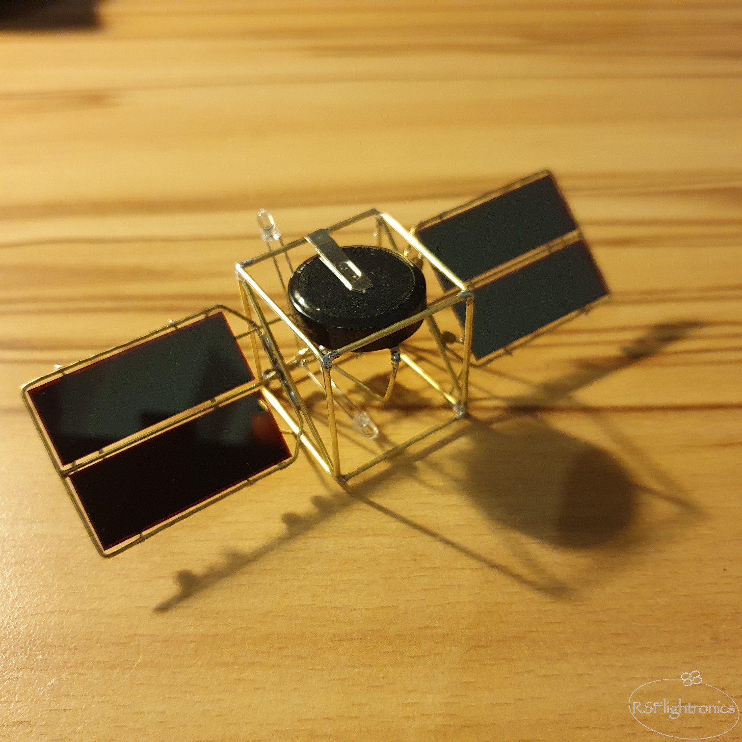
Since the whole sculpture is made out of conductive material, we run into a problem when trying to integrate our solar cells to the main frame. Using an small axial capacitor solves the issue since it gives us solid connection to the isolated pole and at the same time reinforces the frame supporting the solar cells. To make sure that the solar cells stay in place I also used some drops of transparent glue.
Assembling the "main board"
The following schematic shows what is going on inside the circuit sculpture
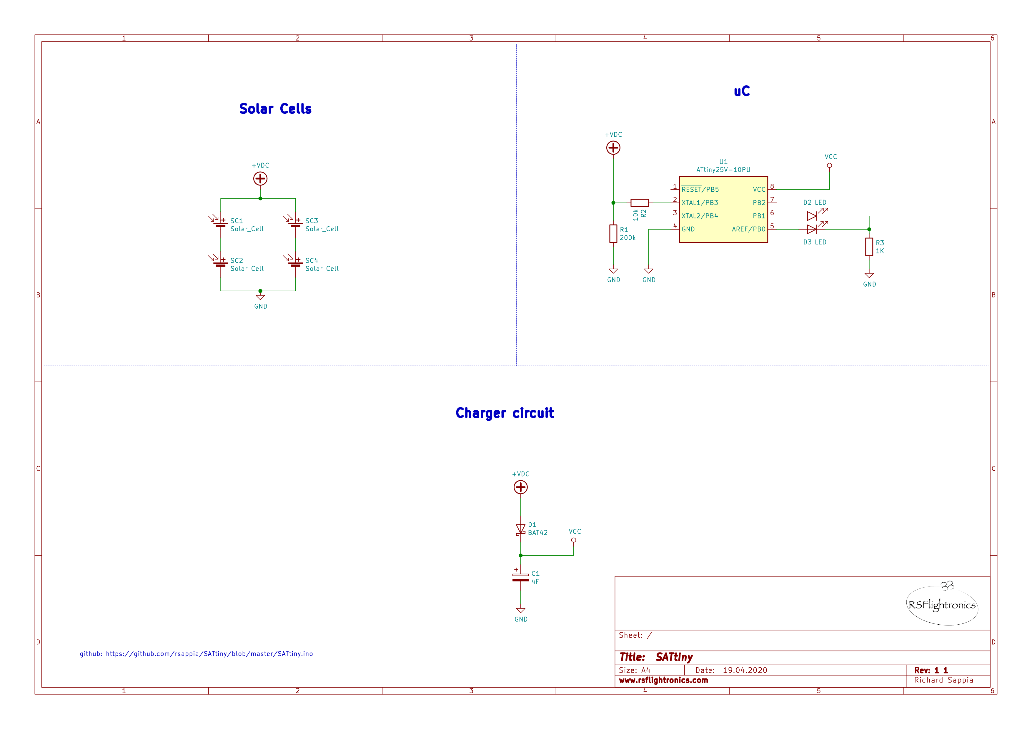
The way the solar cells are connected help to achieve the nominal working voltage for the Attiny25V and also to provide enough current to load the super cap within a reasonable time so when there is no more solar light, the sculpture can run all night long. I live in Germany and cloudy days are very common here... this hasn´t been a problem so far! The sculpture manages to blink up to 7 hours :)
The diode BAT42 is a schottky diode. This diode act as a valve in a way that allows the current to flow from the solar cells to the gold cap and at the same time it prevents the load from the gold cap to go back to the solar cells. I have experimented with different values of gold cap and I was happy with the results obtained with 4F since it was a good compromise between size, load time and the most important... blinking time!
The core of SATTiny is a Attiny25V from Microchip. I chose the V variant since it can work with lower voltages, and this helps when to seize most of the available load in the gold cap.
The uC checks every 8 seconds if the solar panel is feeding the gold cap. If this is the case, then it goes back to sleep again. In case the solar panel is not getting enough light, then the uC switches to blinking mode according to a predefined blinking pattern. When the LEDs are turned off the uC goes back to sleep in order to save energy. The average consumption is around 4uA when sleeping.
Please notice that the blinking time will also depend on the LED color. The red one will last longer since it requires the lowest Vf. If you are ok with a shorter blinking time, you can experiment with other colors and blinking patterns.
The software can be found in my GitHub page:
I preprogrammed the Attiny25V with an Arduino MEGA board before soldering it together with the other parts.
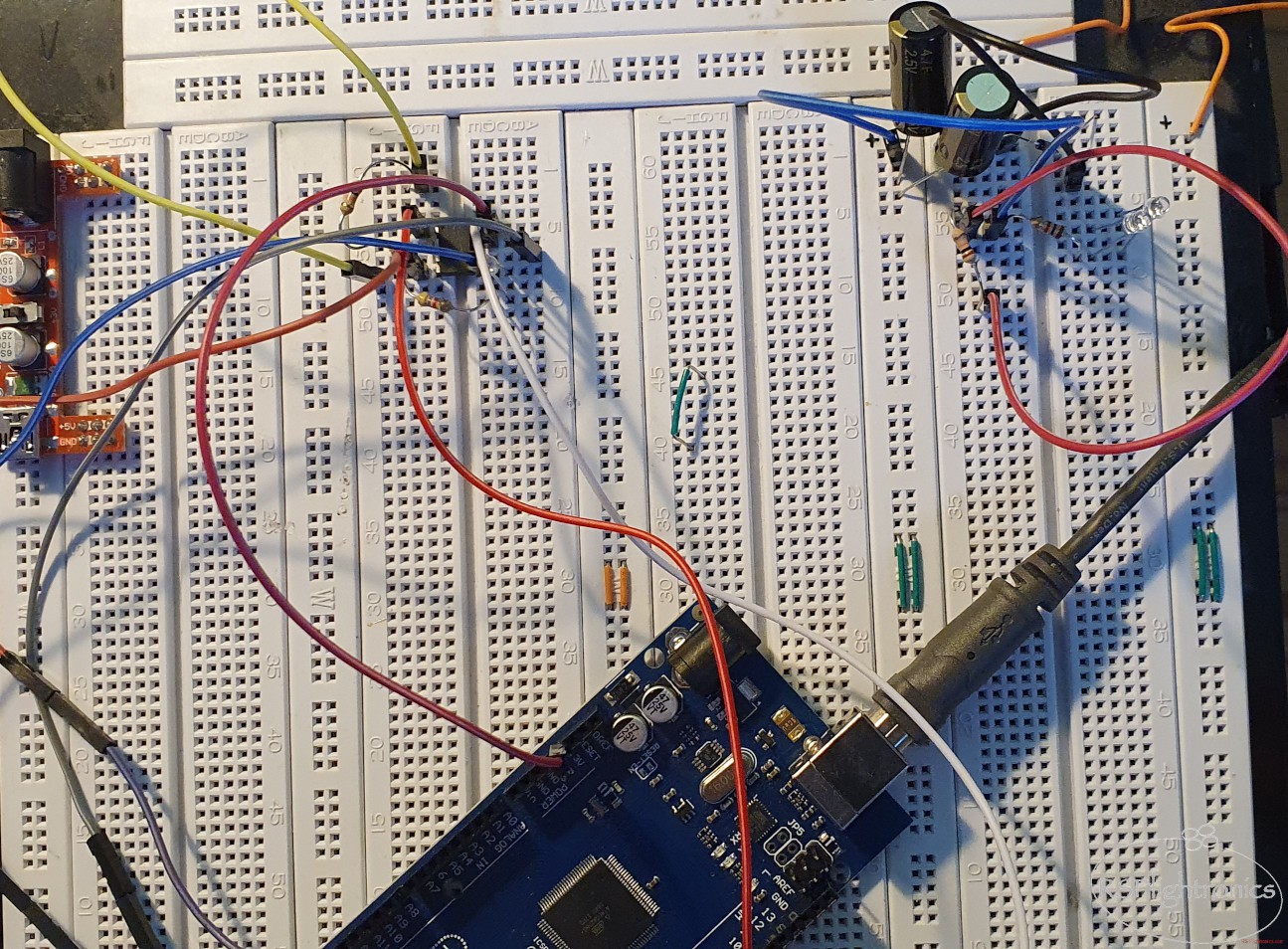
For the assembly a protoboard can be used as guide.
Putting all together
Once all the parts are assembled, they can be integrated. Here you have to have a firm pulse to wire the solar cells pins to the main circuit and to the gold cap.


Testing!
Final words
Putting all this small parts together in a free form format has been a quite challenging, but the results have been way better than expected for a first project like this. It is a great project to proudly...
Read more »


 Serhii Trush
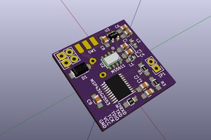
 Andrea Console
 C.Savage
Probably should mention the Arduino board library is the ATTinyCore. If you haven't set any fuses, the attiny25v will be defaulted to a 1 MHz internal clock, so you should probably set accordingly.