 Paul McClay
Earlier this year..
The CNC mechanics of #Minamil: a minimal CNC mill had been working encouragingly well for a while but depended on a bunch of other stuff that could be integrated into a compact enclosure but wasn't. A few months ago I made a new XY stage with longer leadscrews that couldn't fully extend within the frame/enclosure I was using at that point. In the parallel universe where I have better executive function, I simply put the new CNC mechanics in the old box for initial testing with useful if not maximal X range and -- as it turned out -- more work to get it the new thing working as well as the old thing. Instead I started thinking about a different enclosure and that got out of control for a while before I got back to getting the actual CNC part to work.

That was a usable first draft and useful for finding pain points to motivate a second try.
Unfinished bits included:
- switched AC for spindle still not inside the box, but at least consolidated to a hacked power bar
- negative ventilation motor wired but filter & outlet not done
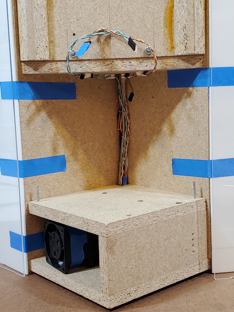
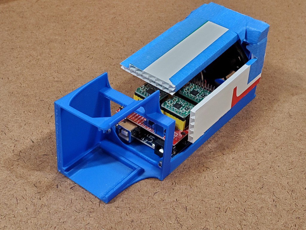
In addition to supporting the CNC parts, the box encloses spaces in the top and bottom. AC power stays isolated in the top part. The bottom part is divided into space for the air filter/fan and space for the control electronics.
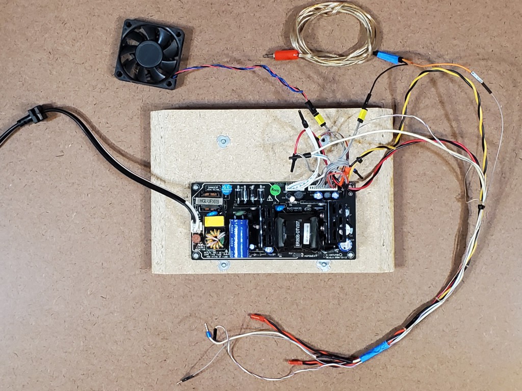
A scavenged unenclosed 5V/12V supply with output through PCB headers and lots of little wires doesn't help the top end look any less chaotic inside. At least it keeps AC away from the rest of the works.
I figured everything should fit and I've already learned that wires fill more space in real life than in diagrams, but once again underestimated the challenge of connecting lots of things in a small box.
Doing this once spawned ideas for how to do essentially all of it differently. I really super very much wanted to do a completely new build that I thought some people might appreciate at MRRF this year -- with fairly specific plans and seemingly adequate time. But life. So less time. So when I did get some time I spent it furiously scrambling to finish just a few betterments before MRRF instead of writing log entries. At least I took some pictures while tearing down the "first draft". Then MRRF. Then more life. RIght now I have some time, and a backlog of ideas. But with this year's HaD Prize "Gearing Up" challenge on, it's time to squeeze in some writing too...
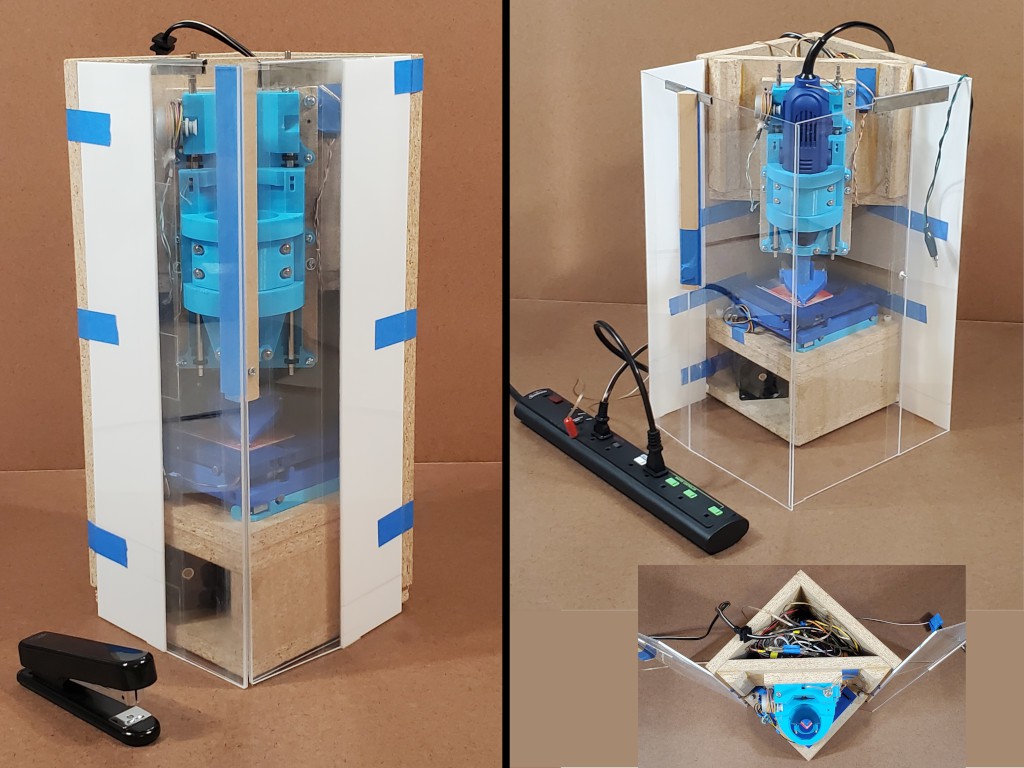
New box, and first try at getting more stuff inside the box
yes, the picture is a repeat -- because a bunch of words got in here after the first instance.
Part of the main idea is for the closed box to be just another box and trivial to stash away wherever without snagging or squishing vulnerable bits.
With the box closed up, I want four flat sides like a plain box with no projections. No hinges, no latches, no buttons, etc. And I want it to be not fragile. In this iteration, moving the hinges away from the corners makes those two corners not fragile. Also the corner where the doors meet is not fragile in compression because the solid panel of each door transfers the load straight into solid material at the hinged corners. For a quickie solution in this case, a single magnet and iron peg (i.e. screw) hold the doors closed, but I have ([1]had?) a plan for a more robust closure. The block in the corner where the doors meet I cut wrong. The idea was to have a single solid piece with the bottom end aligned to rest on top of solid material next to the XY table and the top end in the plane of the top of the box so that, along with the two solid sides of the square, the top can bear load if whatever lands on top has a flat bottom.
Also I have ([1]had?) a plan to replace the metal top clips that hold the straight sides straight when "open" with a closure for the enclosure that would hold the two panels perpendicular where they meet when functioning as a enclosure for the running machine. That's a little tricky because stuff can attach to those panels only on the outside (the sides that face outward in the "open" but "closed" configuration -- err, top-right in the montage above :-/ ).
I really like how this arrangement (and modestly improved next rev) closes up into a very solid box of flat sides ( ̶ ̶i̶n̶s̶e̶r̶t̶ ̶ imagine gif of me vigorously bashing the fragile-looking corner where the doors meet), but it's not clear that clear packing tape hinges can really be a thing (you know that box that's sat by a sunny window for a couple of years...) and I haven't yet found a more respectable hinge with similar function. So this might fade into something sadly less elegant. (...accidental segue to footnote...)
[1] But I might change how the doors fold which would change how the closure works, which would make that idea obsolete. So maybe not building that will be the answer anyhow.
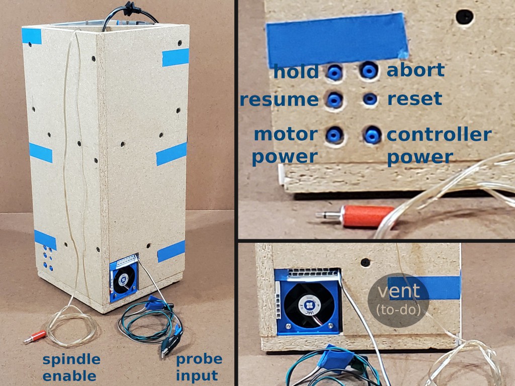
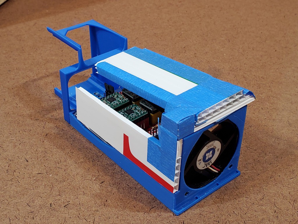
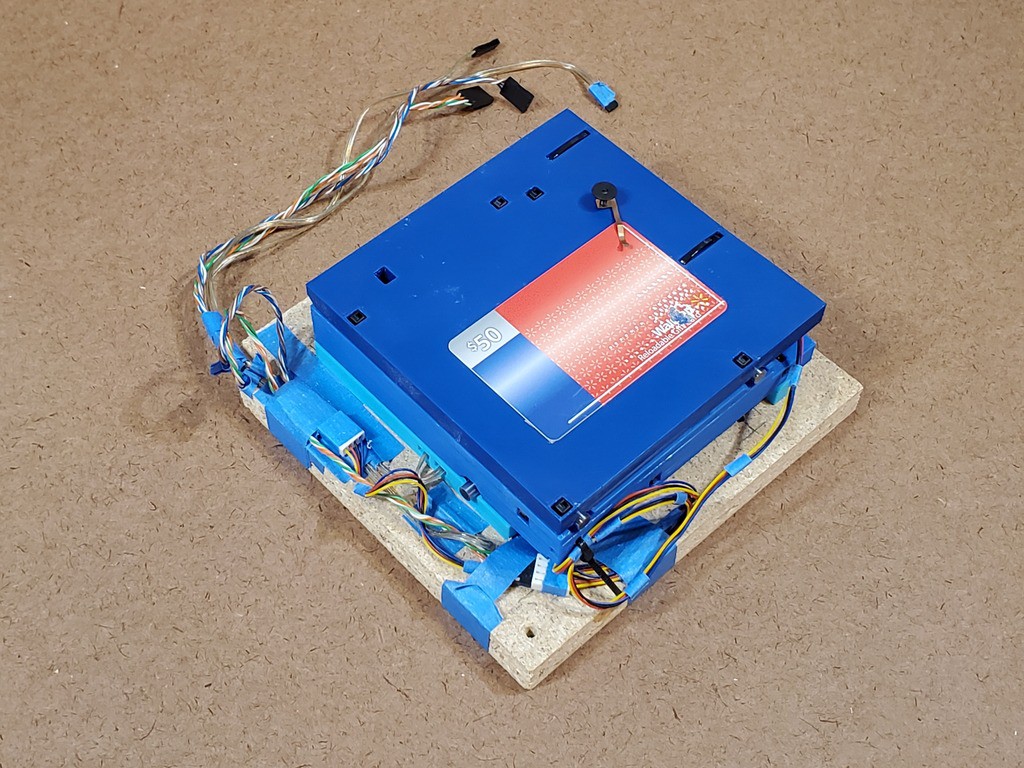
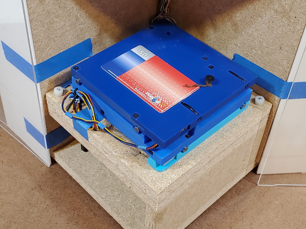
The control electronics all live on a long "sled" that slides in from the back. The blue square with the fan. Status LEDs show through the front. Electronic switches on the sled line up with captive mechanical pushbuttons in the side panel. More pix below.
The control buttons, including push-on-push-off switches, are (supposed to be) slightly below flush with the panel side when "out" and surrounded by fingertip-size relief to allow pressing them "in". Except for reset which is shorter with less relief around so that it requires more deliberate effort to press.
They are out of sight but easy to reach (assuming operation with the solid walls to the right and back and the enclosure panels to the left and front). The hold and resume buttons are at the heights of index and middle fingers for a standard hand (i.e. mine) resting on the table.
"Plans" include adding more tactile cues to help fingers find the buttons quickly. Mainly to confidently distinguish the hold/resume/motors column from the abort/reset/controller column without feeling around. Another idea was to make a removable oversize cap for the abort button to hit with a blind slap then remove and stash in the box when not in use. That might work as the 'tactile cue' if not too sensitive to off-axis touch by a finger sliding along the panel surface.
This arrangement might turn into just a bigger hole in the side panel to expose a solid control panel on the sled. Reasons for not doing that in the first place have faded.
Probe input wires hang out the back because I forgot to decide where to put an accessible connector in the front. Probably because I had "3.5mm jack" stuck in mind and I'm out of panel mount 3.5mm jacks. Meh.
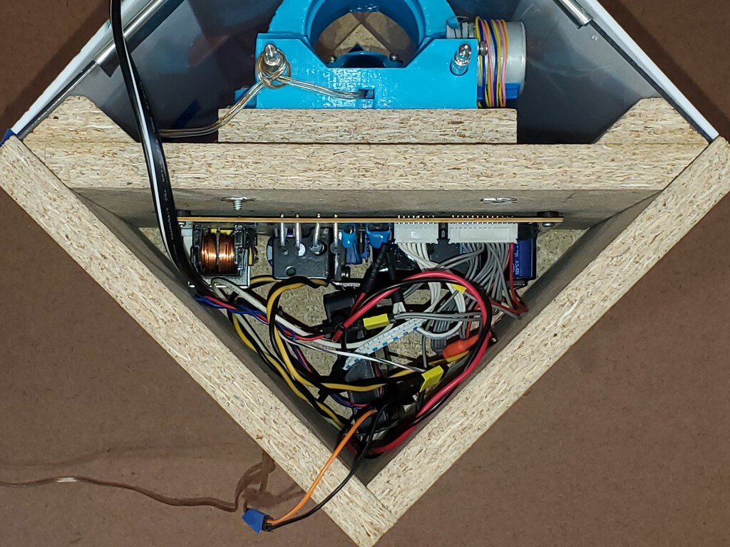
Top: AC / high voltage stuff
I haven't measured current draw for the CNC electronics and (very small) steppers, but I think it's well under 1A. The main DC load is the big fan to suck lots of air through a non-H(igh)E(fficiency)PA filter. That's labeled 3A, but I measured ~1.5A running. Spin-up, although slow, is still faster than the meter I was using so I won't bet that it's any less than 3A. Plus a couple of smaller fans (chip blower & confined electronics). DC draw in steady state might be as small as ~2A. Considering low precision guesses and fudge factors, call it 3-4A. And power supplies that don't specify "yes, Virginia, this really will put out {x}A forever even in a stuffy box" probably won't. That got me to looking at 5A (60W) supplies and up, which looked like I should expect to put a "real" supply in this space rather than a barrel jack.
For a first whack, I found a 5(ish)V+12V power supply from a dead TV that fit.
I want to keep this space isolated from the work area so no vents in the bottom or "front" (diagonal) faces. I didn't know yet how I was going to do the spindle AC stuff or wire a more permanent DC supply that probably would end up needed switched AC (this one has standby 5V and an 'enable' input so I could get this far without an AC switch) so I didn't want to perforate the other two sides yet either. Sticking a power supply down in the bottom of a deep hole seemed a bit rude. So there's another 12V tap and a little fan down there to stir air and make me feel better. I haven't finished the air filter yet so the big fan remains idle and this supply probably never made noticeable heat anyhow.
The spindle enable signal runs up here from the controller below and there's a 12V tap for a relay. But I didn't get that part done. Instead the dangling wire combines the enable signal and ground from the relay supply to drive a hacked power strip for a half-way solution. The power strip has screw keyholes and I could have stuck it to the back of the box if I had reason to carry it anywhere at the time.
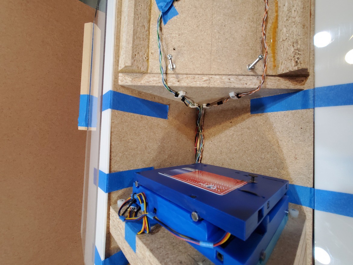
Supply and signal wires drop through a small hole (mostly full of wires, not a vent, and ideally would have some gap fill around the wires) in the corner and run in a tight bundle (an overwrought experiment in flat lacing -- would have been better if I'd read up) down the corner of the box through the messy place to the electronics in the lower compartment.
Another look at what was in the top compartment:
This part was all very "first draft" and already gone. But that's another log.
Laced bundle:
- down: 5V/Com, 12V motor supply, separate 12V/Com for the big fan
- up: power enable (12V & more 5V), spindle enable
That bundle runs straight down the back corner of the work area to the Grbl sled below:
(shown with Z axis wiring also)
Bottom: DC / low voltage stuff
aka Grbl sled
So, the supply wire bundle comes down from the top to this "sled" that slides into a pocket in the base of the box. Status LEDs line up with holes in the front and switches on the side line up with captive buttons in the side of the box.
And a bunch more wires go back up through the same hole into the work area above. Except power for the big fan which goes over to the other side of the box base.
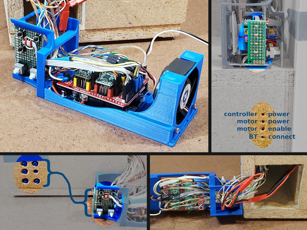
Push-on-push-off switches:
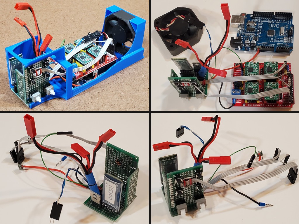
- 5V to controller (Grbl on Uno clone + Protoneer-designed CNC shield + A4988s)
- 12V enable signal to power supply
When the supply is not "enable"d, standby 5V (>6V open circuit - which exceeds "absolute maximum" for the mcu so minus a diode drop) provides enough juice to keep the controller & bluetooth alive. Barely. That load drags the voltage down to I forget what but well under 5V (before add'l diode drop). Setting the "enable" signal to the PS lights up 12V and solid 5V.
The compartment gets really crowded with wires:
- bundle from the top compartment
- switched 5V to controller
- 4x 4p stepper cables (support for redundant Z motor)
- 3x 2p limit switches
- 2p switched chip blower far
- spindle (& chip blower) enable
- fat 2p switched vent fan
- vent fan enable
- 2p sled fan
- TX/RX to BT module
- motor enable to status LED
- 4x tact switch (hold/resume/abort/reset)
- ground to CNC shield (also grounds controller)
Part of making all that fit was running all wires that leave the compartment up to the front of the sled. From there all the wires run in a somewhat parallel bundle about the same distance back to where they go up (or sideways) out of the compartment. Then when the sled is in place there isn't a lot of extra wire in where there's no extra room, and that length of wire allows the sled to be pulled out without disconnecting anything.
Another part of making stuff fit was concentrating the off-controller stuff -- LEDs, switches, fan FETs, BT module, etc -- in a single compact unit with no bulky wire terminals, few 0.1" headers, and lots of short pigtails. Three chips of FR4 perf board hold switches on the side, LEDs to the front and everything else (fan FETs, a few interconnect headers, and lots of interconnect pigtails) on the bottom. Through-hole switches and big FET for the big fan; otherwise SOT-23 and 0603 SMD.
Yeah, that, and ...
I want to get more pictures in here since they're what's left of that build but I need to get past this log entry which means fewer words. Which probably will mean more future forgetting what was what and why. Meh.
Fans
- upper/AC/power supply compartment -- described above.
- sled compartment
- dust suction (switched as "coolant")
- chip blower (switched with spindle)
The sled has a fan. The controller probably doesn't make much heat and the motor current is small so maybe this doesn't matter. But it's a crowded confined space. So a fan makes me feel better.
This iteration was a ̶c̶o̶p̶ ̶o̶u̶t̶ ̶ experiment to avoid making holes when I don't know what I want to end up with. The fan exhausts air out. The fluted sign board lets makeup air in past the electronics so that it goes back through the electronics on the way out. Hopefully with sufficiently little resistance to avoid sucking cutting dust in through e.g. the LEDs. I tried to see if blocking these inlets reduced airflow out. Inconclusive. Experiment over. The sled wasn't full of dust after as much use as this version got. Next iteration turned the fan around to pressurize the compartment (with clean air) so dust won't (isn't expected to) be a driver of where to put outlets. Or maybe LED & control openings will be enough.
This was supposed to be fewer words....
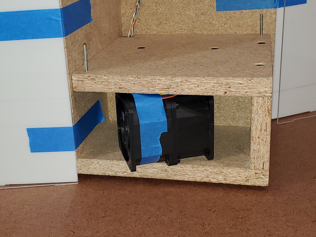
Dust suction
Sucking air down into the enclosure and through a filter on the way out worked quite well in earlier builds. ATSM level 2 surgical mask is about the right size and supposed to filter mean micron & sub-micron particles pretty well. But it's far from "High Efficiency". This power-dense counter-rotating fan drives enough static pressure differential to get the job done. It's also crazy loud -- which matters little for an intrinsically loud application.
The fan is wired with plenty of power thru a hefty FET switched by Grbl's "coolant enable" signal. But I haven't made a filter frame or exhaust opening yet. ... must. escape. this. log. first. ....
![]()
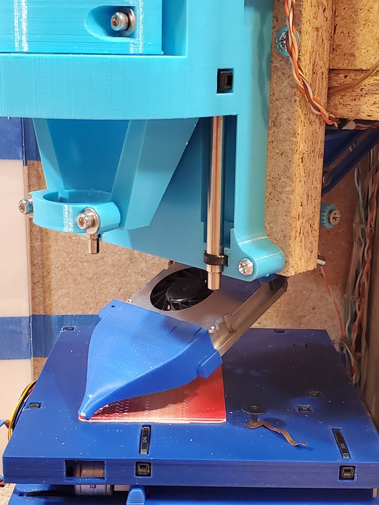
Chip blower
Blowing a weak air stream from a weak air pump through a tight nozzle directly at the tool tip worked pretty well in prior builds, but that was one of the worst offenders among things that in principle could be integrated into a compact box but was awkwardly not.
I thought some thoughts about that for a while. So far that's lead to fixing a nozzle directly to a "turbo"-type (side exiting) blower and suspending that assembly on a 2dof rig behind the spindle. Found an old laptop cpu cooler for a first draft.
low / thin material:
high / thick material (tight to bottom of Z but still reduces Z clearance but still much more Z clearance than thickness of anything I've tried to cut so far):
max high/retract:
the rig:
- hidden vertical-ish slot in moving piece crosses horizontal-ish slot in fixed piece for 2dof
- constraint-solving parametric CAD FTW!
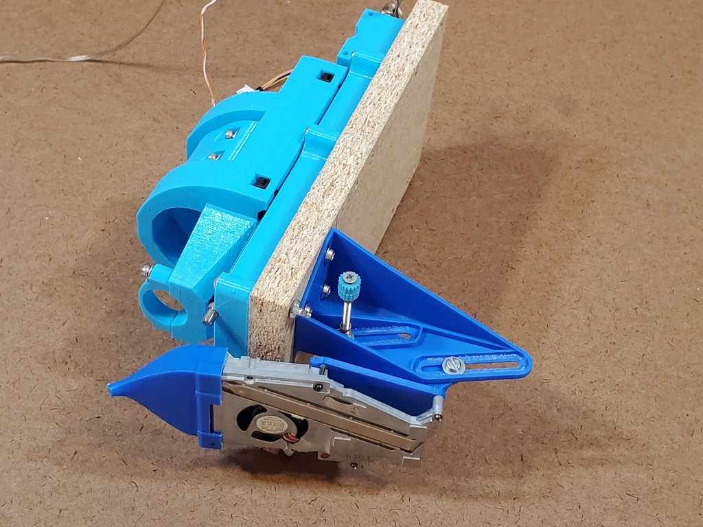
Hey look... Is that Z axis attached to a removable frame part?
XY axes
While iterating the axes the mounting screw pattern keeps changing. That means a mess of holes in the prior couple of frames. I've tried to set and keep a uniform pattern, but the uniform pattern keeps changing. Hole entropy only increases.
Also, adding flanges for mounting screws makes the XY table more sprawly, which limits shrinking the overall footprint. Running screws up from below into the bottom of the XY unit would solve that, but no access from below without impractically much dis/reassembly.
Also, I wasn't having great ideas for how to reach the back or right sides with a drill or sensible screwdriver without impractically much dis/reassembly.
Also, I'm more interested in smallness of footprint than shortness of height. So adding ⅝ in. more tallness doesn't break my heart.
So the XY table attaches, from below, to a separate piece of frame material that can be replaced when it gets too perforated...
 ...and which is stiff enough to pin down with two thumb nuts in the reachable pair of opposite corners.
 Actually this "first draft" started with wing nuts instead of thumb nuts. That worked. But they need a lot of room for the wings to swing. This version has the room but I was thinking of a frame shrink before MRRF. When I get to that, it will require something more compact. These thumb nuts are the current candidate for that.
XY cable dressing remains an unsolved mess in this version. There's no room for excess wire below so excess, and connectors, get tapewadded up on top. Also installing/removing this unit requires hauling out the Grbl sled and fishing wires with big ends made of edges and corners down or up through a crowded hole. Lesson: wires that leave the Grbl gaol have to be disconnectable at both ends. Also lesson: unless they're exactly the right length and can be dis/connected in tight quarters, the XY assembly needs some provision for managing a little extra wire + connectors above the deck but not interfering with motion or limiting footprint shrinkage. As a separate concern, the motor wires come down to the deck at a specific point near the left edge; it would be nice to have a more deterministic fixture there.
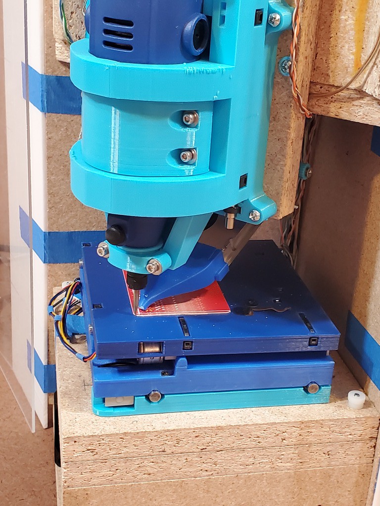
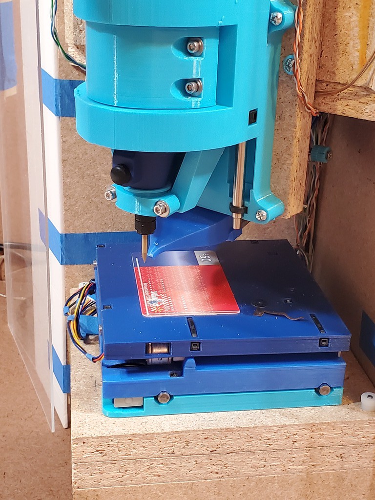
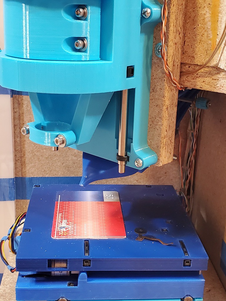
The Walmart card is my spoil board for now. It's smaller than the usable work area so that's not a complete solution.
The little spring contact under a shoulder screw helps with Z-probing copper-clad board. The springy part contacts the board and the Z probe -- so far just an alligator clip -- can clip to the shoulder screw.
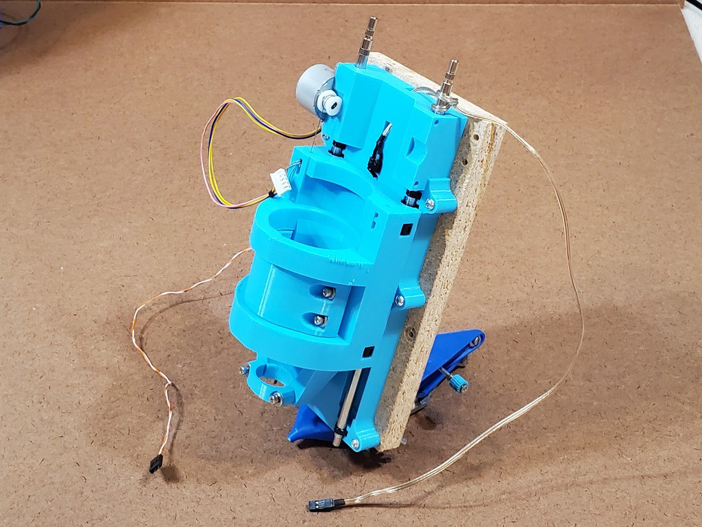
Z axis
The Z axis attaches to a separate plate also. Along with solving screw hole entropy, this also adds stiffness behind the part of the axis that projects below the fixed upper face of the frame so the printed part doesn't have to handle that by itself. T-nuts in the frame make it easy to zip this on/off with machine screws run into threads that aren't fragile. Also, I cleverly marked out and drilled the screw holes in the frame with just the Z base attached to the detached attachment plate. So there's plenty of clearance around the attached base of the Z axis for the screws that attach the assembly to the frame -- provided no steppers or sliding part of the axis are attached. Besides forgetting about motors, I forgot that the moving part is a little wider than the fixed part. It's just possible to sneak the bottom two screws past the moving/tool-holding part, but the motors completely cover the upper two screws. Bah. For slight relief, I've been running this Z axis mostly with one motor (it suffers less from reasons to want redundancy in earlier versions) so at least one upper screw is easy to use and that's not very much less stiff than with all four screws. So hole entropy in the frame will soon increase anyhow. I've already cut a new (what to call it?) intermediate plate that's a little bigger to spread out the screws a little more.
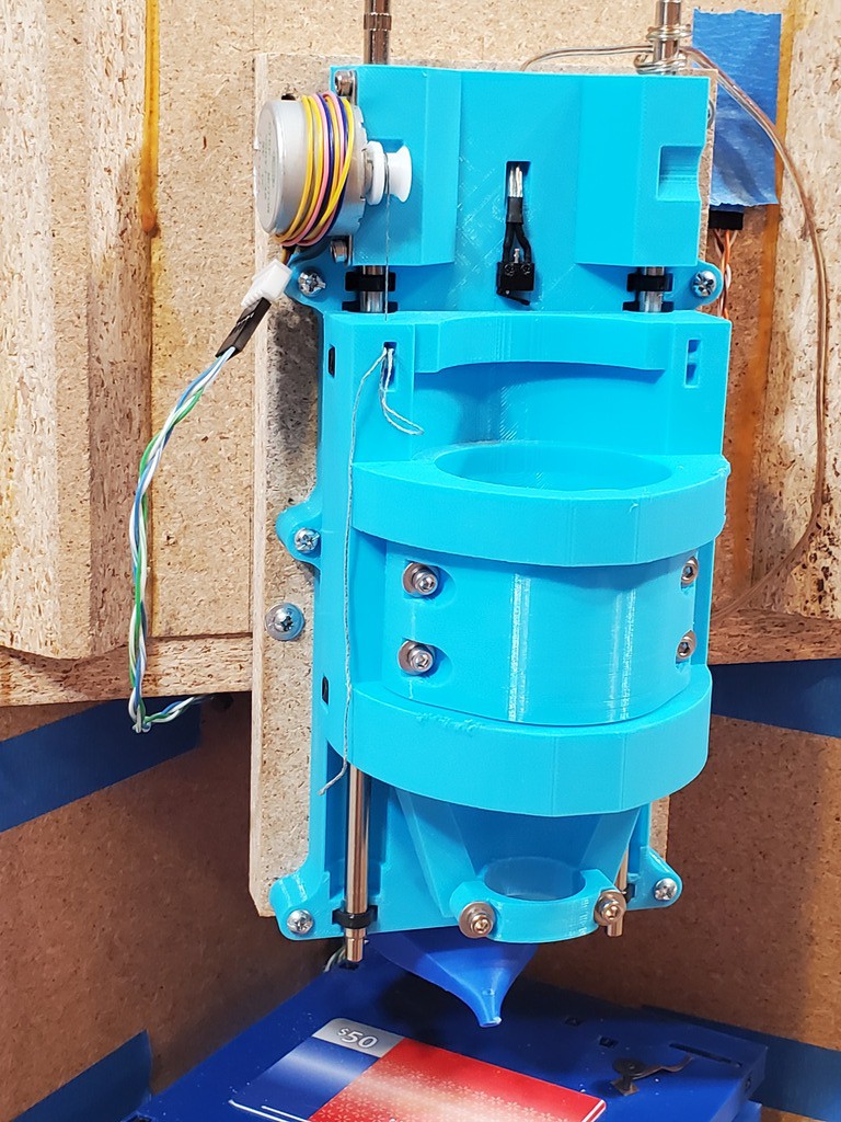
I randomly found a box of wire clips at a resale shop that looked like a good candidate for managing the Z axis wiring where it comes to the front from the vertical run back in the corner. Alas, whatever plastic they are made from is crazy stiff and I have to pry them open with a screwdriver to slide wires in/out without scrubbing the insulation -- without crushing wires with the screwdriver that I'm using to avoid crushing them with the clip. :-/
Attaching the chip blower to the back of the Z axes intermediate board seemed like a good idea at the time. Largely because I didn't want to deal with attaching it to the bottom of the upper compartment of the frame. But it makes the Z assembly much more awkward when off the frame. FITNR.
Ok, that was kind of a failure to use less words. But instead got done with less photo editing.
Discussions
Become a Hackaday.io Member
Create an account to leave a comment. Already have an account? Log In.