Subhajit
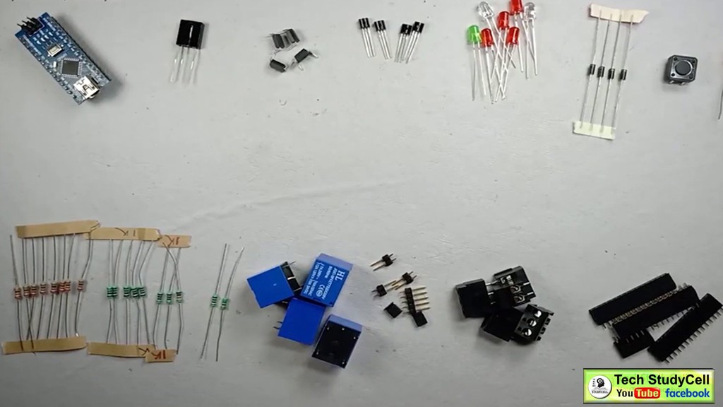
Required Components:
1. TSOP 1738 IR Receiver (1 no)
2. 100uF Capacitor (1 no)
3. Arduino Nano
4. ESP01 module (ESP8266)
5. Optocoupler PC817 (4 no)
6. Transistor BC547 (4 no)
7. LEDs (1.5) (7 no)
8. Diode 1N4007 (4 no)
9. SPDT Relay 5v (4 no)
10. 220-ohm Resistors (8 no)
11. 1k Resistor (6 no)
12. 2k Resistor (1 no)
13. 4.7k Resistor (1 no)
14. 10k Resistor (1 no)
15. Male & Female connectors (2mm Pitch Female BERG Strip)
16. AMS1117 3.3V voltage regulator (1no)
17. Push buttons (2 no)
18. Zero PCB
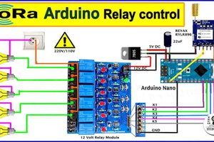
Circuit Diagram
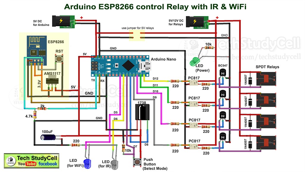
This is the complete circuit diagram for this home automation project. I have explained the circuit in the tutorial video.
In the circuit, the RX and TX pins of Arduino Nano is connected with the ESP01 (ESP8266), So that the Arduino and ESP01 can communicate with each other and we can monitor the real-time status in the Blynk.
A 1738 IR detector is connected with the D8 pin of Arduino to control the relay module from any IR remote (Ex TV Remote).
There is also a push-button to select the MODE.
In MODE-1 we can control the relay module from both Blynk App and IR remote.
And in MODE-2 we can control the relay module from only IR Remote.
In this circuit, we can use both 5V or 12V relay but we have to change the resistors accordingly.
Tutorial Video for this IoT project :
In this video I have explained all the steps in details.
Configure the Blynk App :
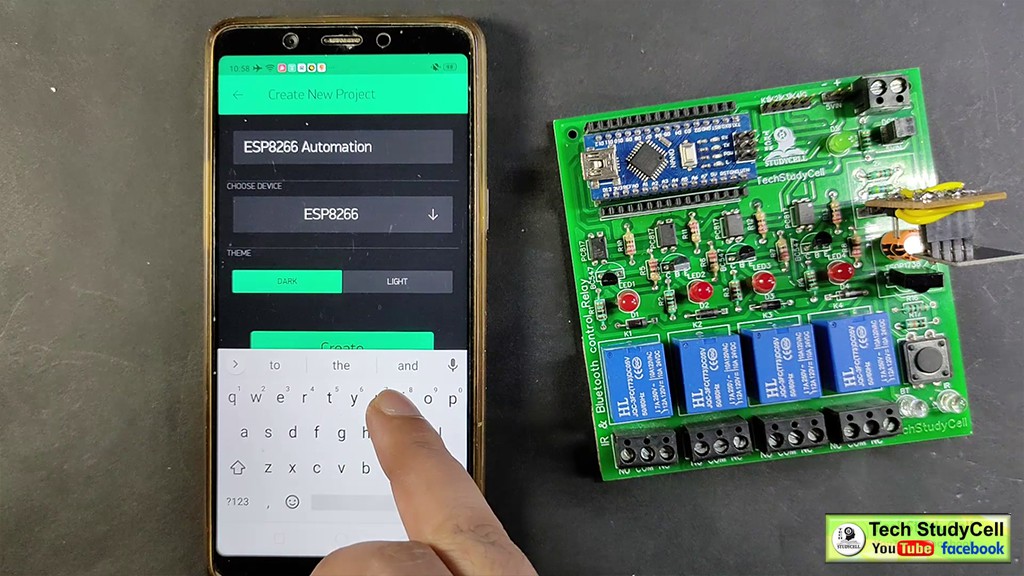
Install the Blynk App from Google play store or App store.
Create a new project (Board: ESP8266 and Connection Type: WiFi)
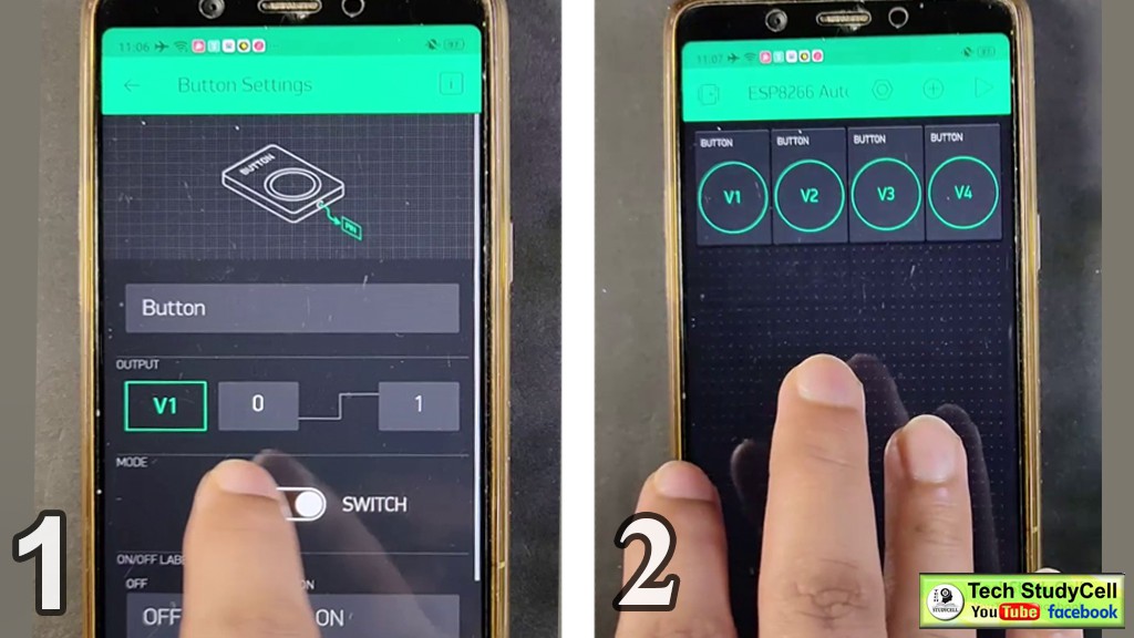
Then add all the 4 buttons with virtual pins V1, V2, V3, V4.
I have explained all the details in the tutorial video.
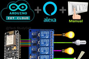
Control Relay Module From Blynk Through Internet:
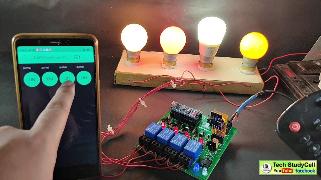
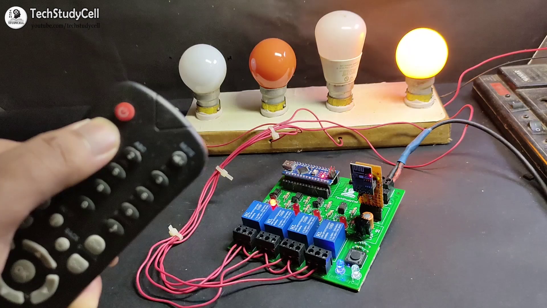
As you can see in the picture, we can easily control the relay from the Blynk App. The ESP01 is connected with the WiFi.
1. When I tap on any button the Blynk server sends the signal to ESP01.
2. Then ESP01 (ESP8266) sends the signal to Arduino Nano through the serial terminal.
3. After receiving the signal from ESP01, the Arduino TURN ON or OFF the respective relay and send the feedback to ESP01 through the serial terminal.
4. When feedback received from Arduino, the ESP01 sends the current status to the Blynk server.
5. Thus we can always monitor the current status in the Blynk App.
So if the internet is available, we can control the relay module from anywhere in the world.
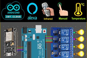
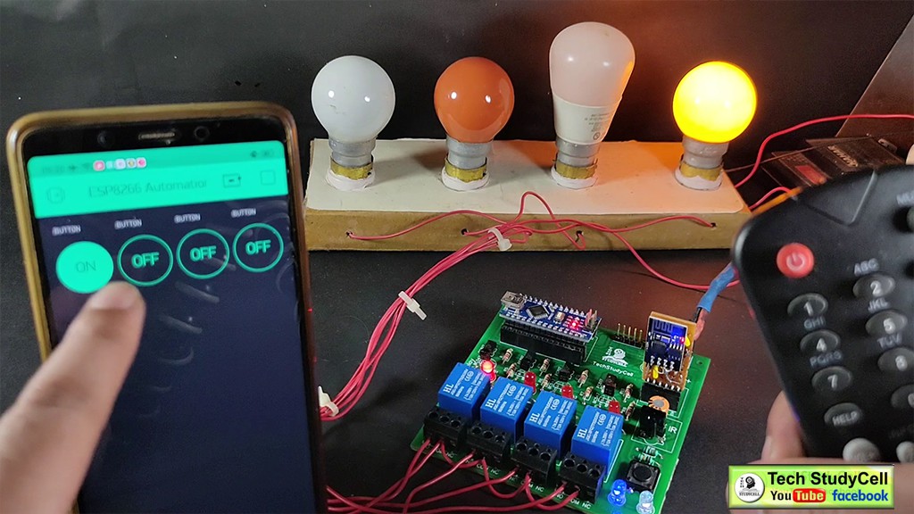
Control Relay Module From IR Remote:
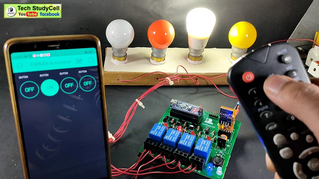
We can also control the relay module from any IR remote. For that, we have to map the Hex codes of the buttons with the respective relay, in the code. (We will discuss later).
1. When I press any button in the IR Remote, it will emit some Infrared signal.
2. The 1738 IR detector will receive the IR signal and send it to Arduino as Hex Code.
3. Arduino first compares the HEX code with the predefined value.
4. If the Hex code matched, the Arduino will TURN ON or OFF the respective relay.
5. Then if the internet is available, the Arduino will send the current status of the relay to ESP01.
6. ESP01 will send the signal to Blynk Server so that we can monitor the current status on the mobile.
Thus we can control the home appliances with IR remote.
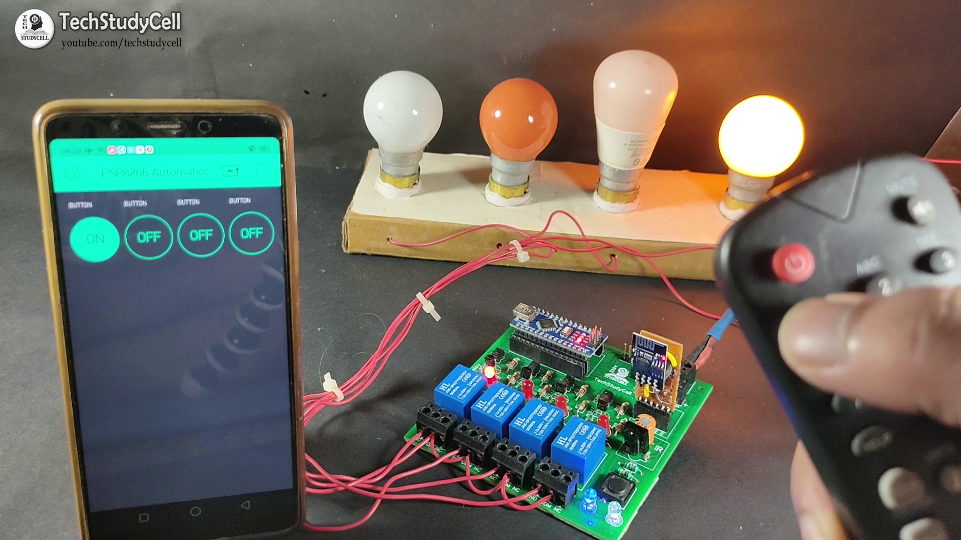
No Internet Mode:
If there is no internet, then we can control the relay module from the IR remote.
When the internet comes back, ESP01 will connect with the WiFi automatically.
Then the Arduino will move to the internet mode and send the current status to the Blynk server.
After that, we can control the relay module both from mobile and IR remote.
Program the ESP8266 (ESP01):
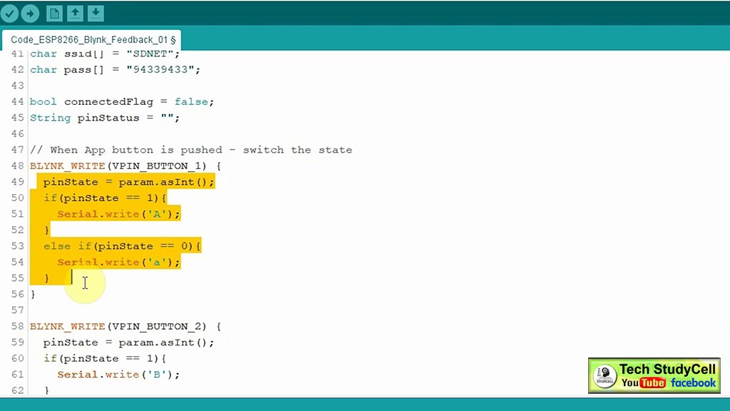
Download the Code for esp8266 and Arduino home automation:
https://drive.google.com/uc?export=download&id=1oEq9iVto-FIraNBZNK-3CK2qXIXOf2m5
1. Enter the WiFi credentials, (WiFi Name & Password).
2. Then enter the AUTH TOKEN sent by the Blynk.
3. Connect the...
Read more »