Subhajit
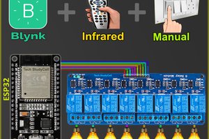
This smart relay has the following features:
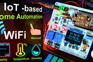
This Smart Home System has the following features:1. Home appliances control from WiFi (Blynk App)
2. Home appliances controlled with manual switches.
3. Home appliances controlled by TV Remote (Infrared)
4. Relays controlled by temperature & Humidity sensor (DHT11) automatically.
5. Home appliances controlled by Dark Sensor (LDR).
6. Monitor LIVE temperature & humidity reading on the smartphone.
7. Monitor real-time status on the Blynk App
8. Inbuilt Arduino so Arduino code can be uploaded to the relay module.
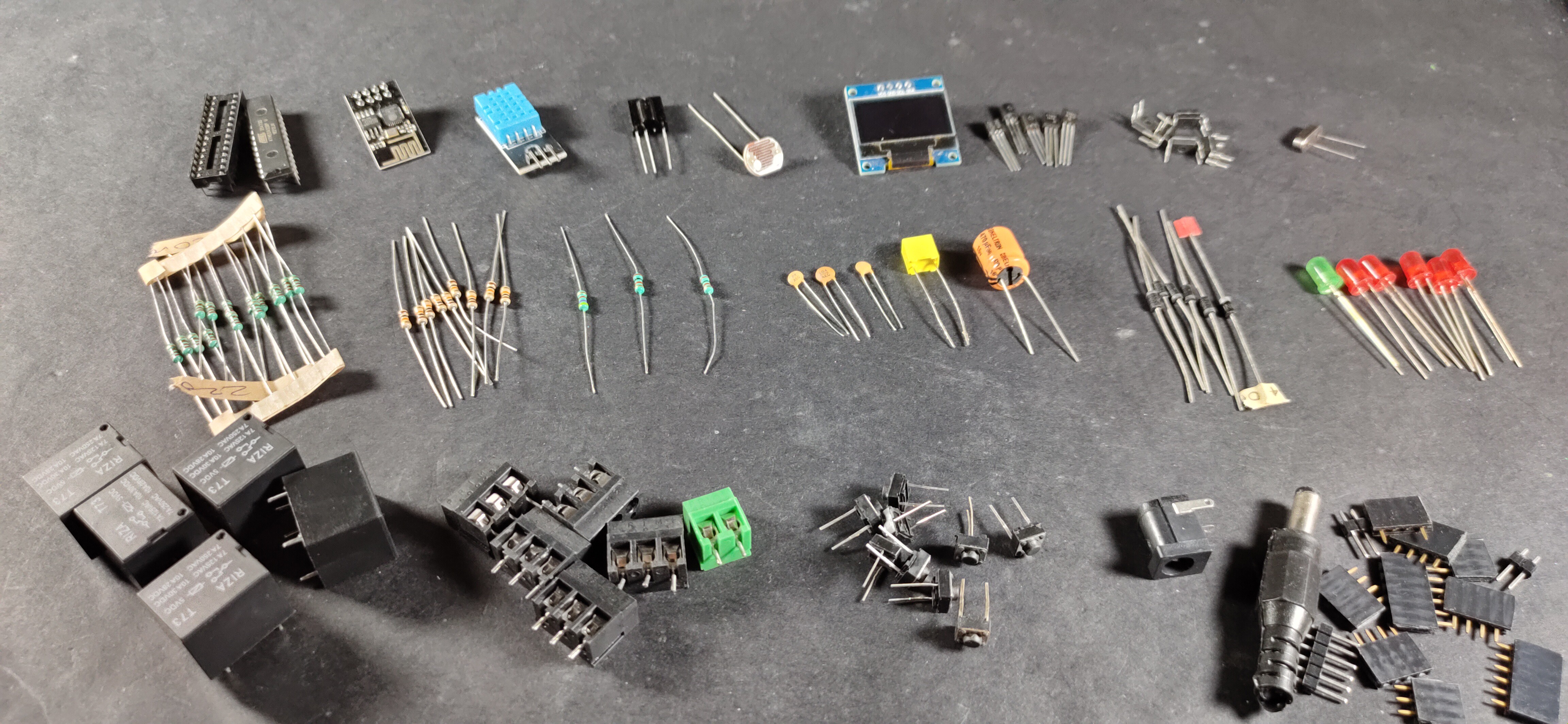
Component List:
1. ATMEGA328P microcontroller with bootloader
2. ESP01 WiFi Module
3. DHT11 Sensor
4. OLED Display
5. 1738 Infrared Receiver
6. PC817 Optocoupler (5 no)
7. BC547 NPN Transistors (5 no)
8. 1N4007 Diodes (5 no)
9. 1N4001 Diode (1 no)
10. LEDs 5mm (6 no)
11. 22pF Capacitors (2 no)
12. 100nF (104) Capacitor (1 no)
13. 470uF 25V DC Capacitor (1 no)
14. 220-ohm Resistors (15 no) (R1-R10)
15. 1k Resistors (1 no)
16. 10k Resistors (9 no)
17. 2k (1no) & 4.7k (1no) Resistors
18. LDR (1 no)
19. 16MHz Crystal
20. Push Buttons (9 no)
21. 5V relays (5 no)
22. Jumper (2no), connectors, IC base
23. AMS1117 3.3V voltage regulator (1no)
24. FTDI 232 USB to Serial interface board or Arduino UNO
Circuit Diagram:
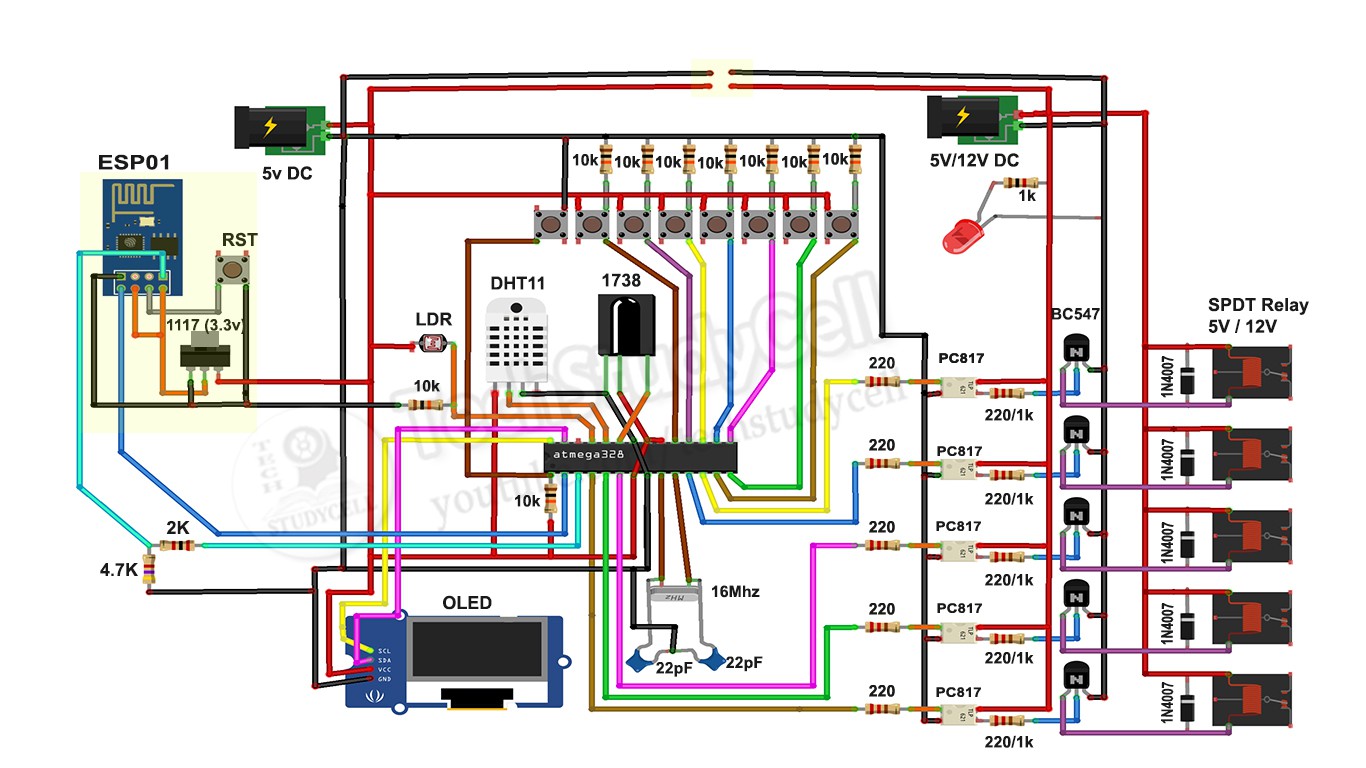

This is the complete circuit diagram for this home automation project. I have explained the circuit in the tutorial video.
I have used the ATMEGA328P micro controller to control the 5 channel relay module. I have also connected the ESP01 WiFi module, 1738 IR receiver to control the relays from Blynk App (Mobile) and Infrared remote. And DHT11 temperature & humidity sensor and LDR to control the relay automatically.
In this circuit, we can use both 5V or 12V relay but we have to change the resistors accordingly as mentioned in the circuit.
Please watch the complete tutorial video where I have explained all the steps.
SUBSCRIBE our YouTube channel for more such projects:
https://www.youtube.com/c/techstudycell?sub_confirmation=1
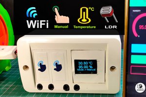
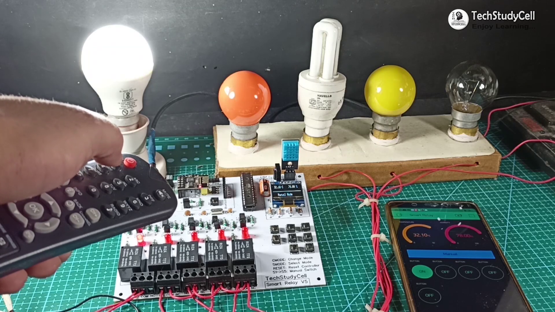
Different Mode of the Smart Relay Module
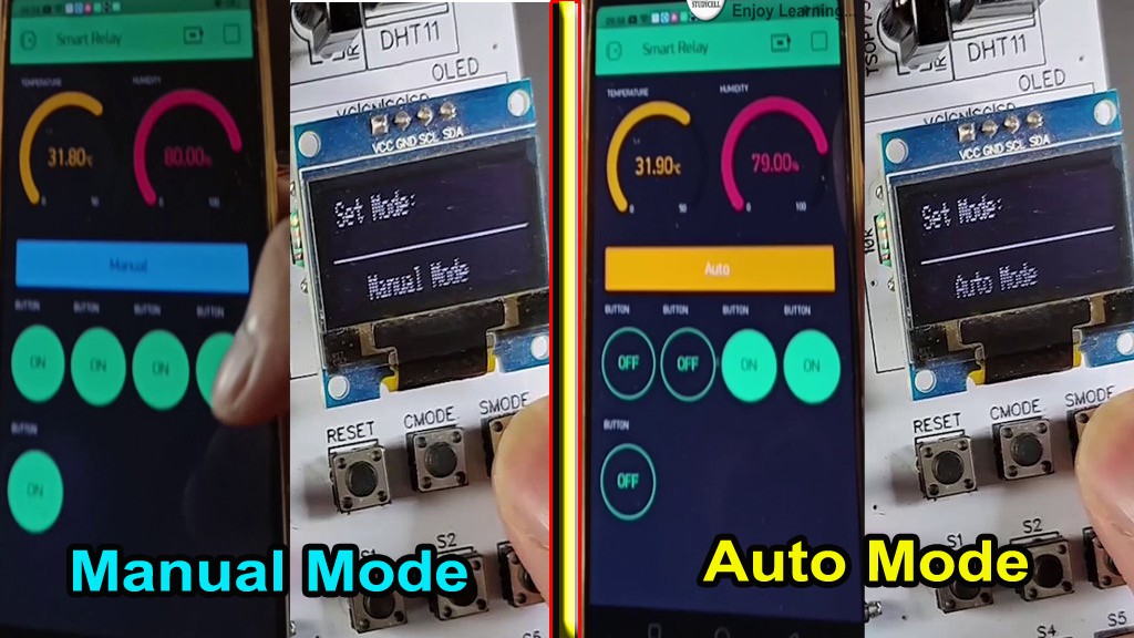
In this Smart home project we can control the relay module in two modes:
1. Manual Mode
2. Auto Mode
You just need to press the CMODE button to change the mode of the relay module.
1. Manual Mode:
In manual mode, you can control the relay module manually from push buttons, smartphone & IR remote.
2. Auto Mode:
In auto mode, the DHT11 sensor and LDR will control the relay module as per the room temperature and ambient light.
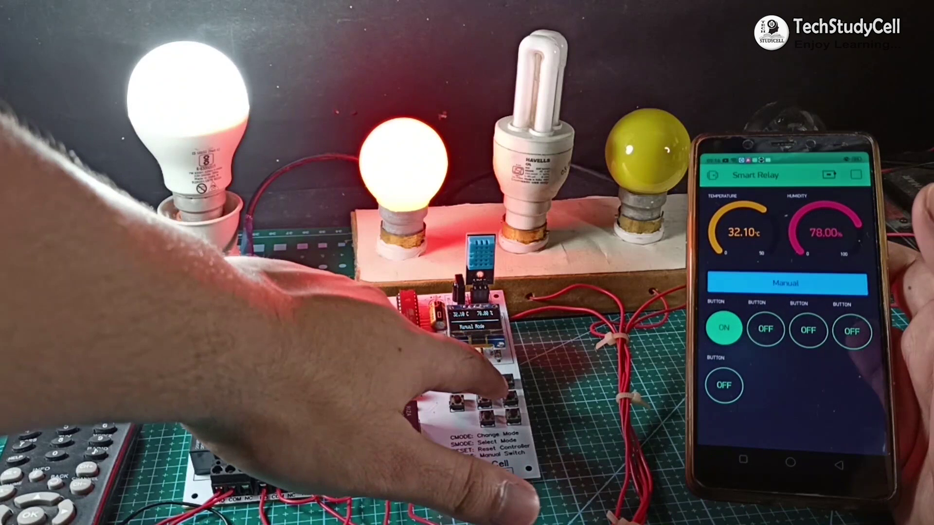
In both modes, you can monitor the real-time status, temperature, humidity from the Blynk App.
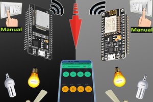
WiFi Control From Blynk App
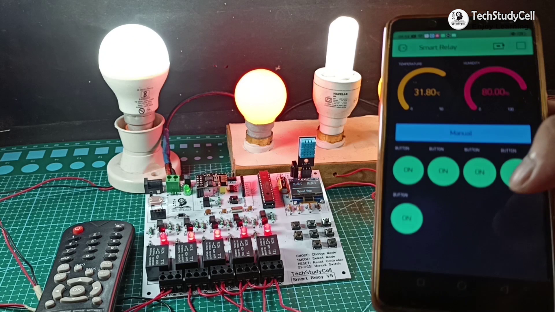
Here I have used ESP01 and Blynk app to control the relay module from the smartphone through the internet.
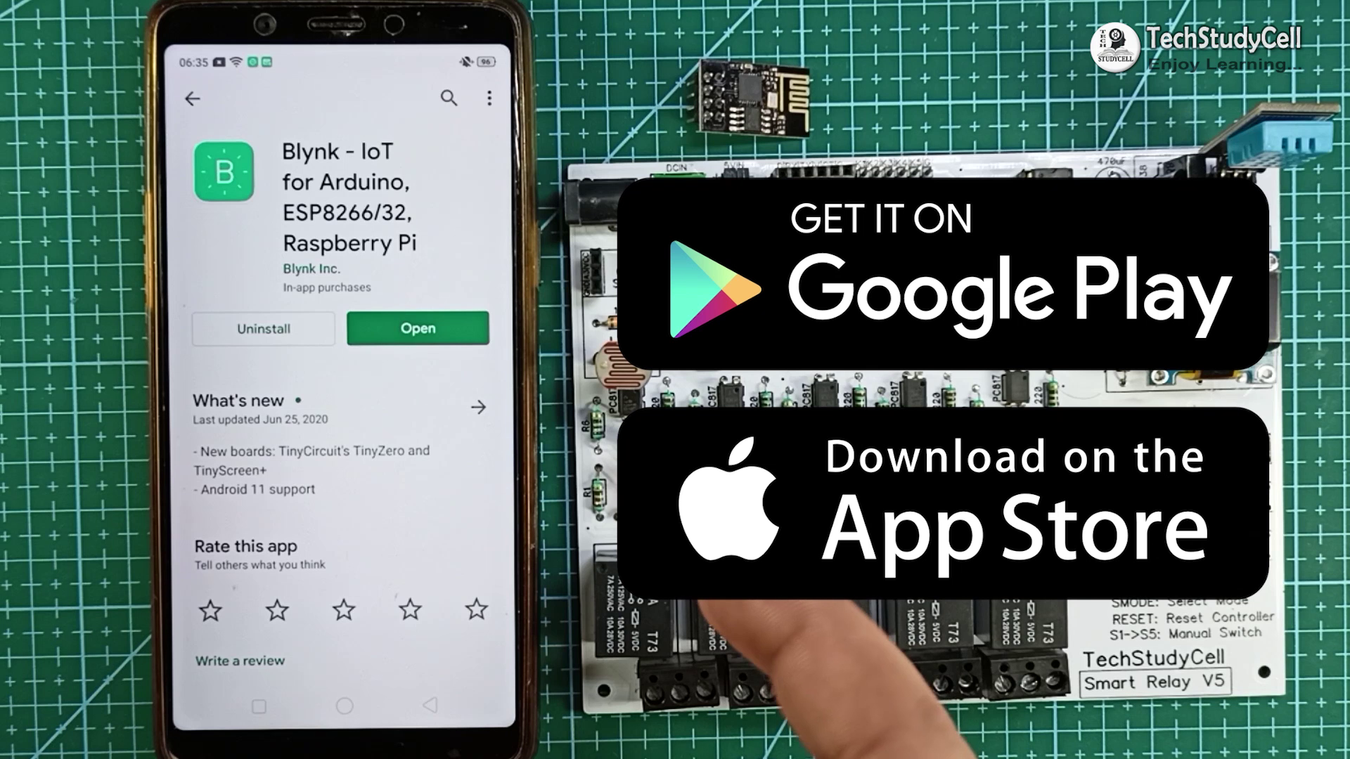
You can download the Blynk App from Google Play Store or App Store. I have explained the configuration in later steps.
As ESP01 works in 3.3V, so I have used the ASM1117 3.3V regulator to drop the voltage to 3.3V.
You can control the 5 home appliances from the smartphone from anywhere and also monitor the real-time status in the Blynk App.
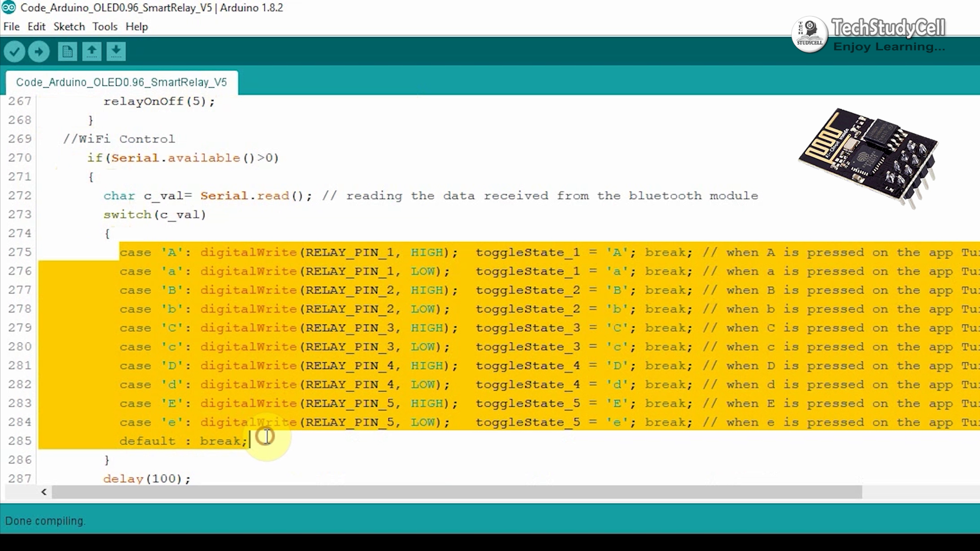
I have explained the code in the tutorial video.
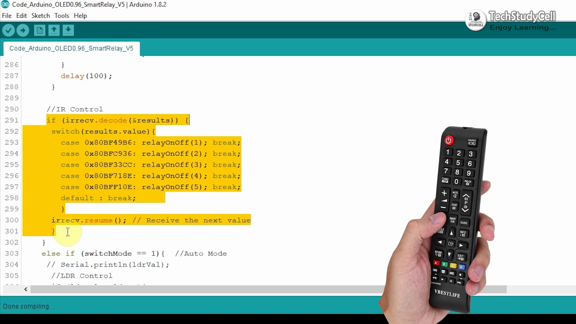
Infrared Control From TV Remote
Here I have used the 1738 Infrared receiver IC to control the relay module from the TV remote.
You can use any infrared remote but you have to get the respective Hex codes of the remote buttons and modify the code accordingly.
You can refer to the embedded video where I have explained how you can easily get the hex code from the TV remote button. You can use any unused button from the remote to control the home appliances.
Manual Switch Control
The Relay module also can be controlled manually from the push buttons fitted on the PCB.
There are 5 push buttons S1, S2, S3, S4, S5 to turn on, and turn off the Relay1, Relay2, Relay3, Relay4, Relay5 respectively.
And there...
Read more »