Close
0%
0%

Remoticon: Basics of RF Emissions Debugging

RF is black magic and we're going to learn about it here!

Public Chat
Similar projects worth following

Workshop Details:

Electromagnetic compliance testing is probably the most sneaky-difficult phase of product development for an electronic design, almost regardless of design complexity. On the one hand, adherence to relatively simple rule-of-thumb circuit design and layout guidelines can hugely improve radiated emissions. On the other hand, the "how" and "why" of those rules of thumb makes very little sense without practical, hands-on experience sniffing emissions. The roles of close capacitor placement, minimized loop area, continuous ground planes, and so on become immediately apparent with actual measurements and observations to back up the sometimes hand-wavey theory, and if you know what you're looking for, these measurements don't HAVE to be unattainably expensive.
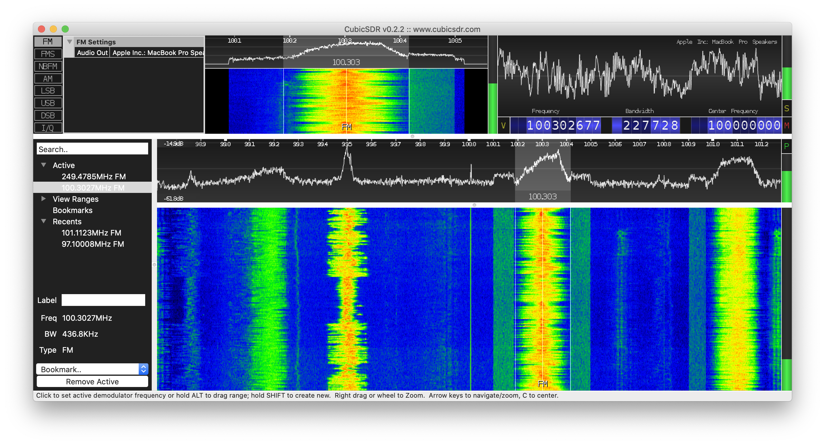
In this workshop we'll explore a background on theory and what we're trying to accomplish, following along with an example failed EMC test report and how to read it.
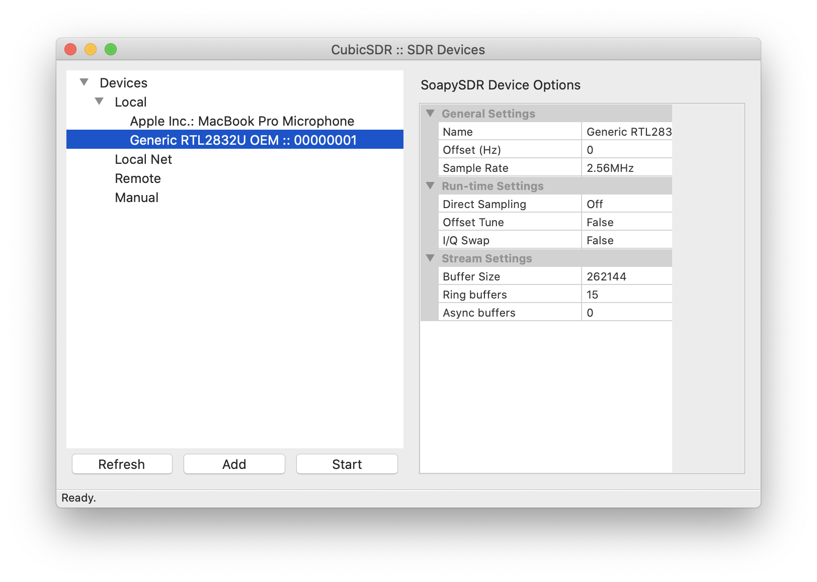
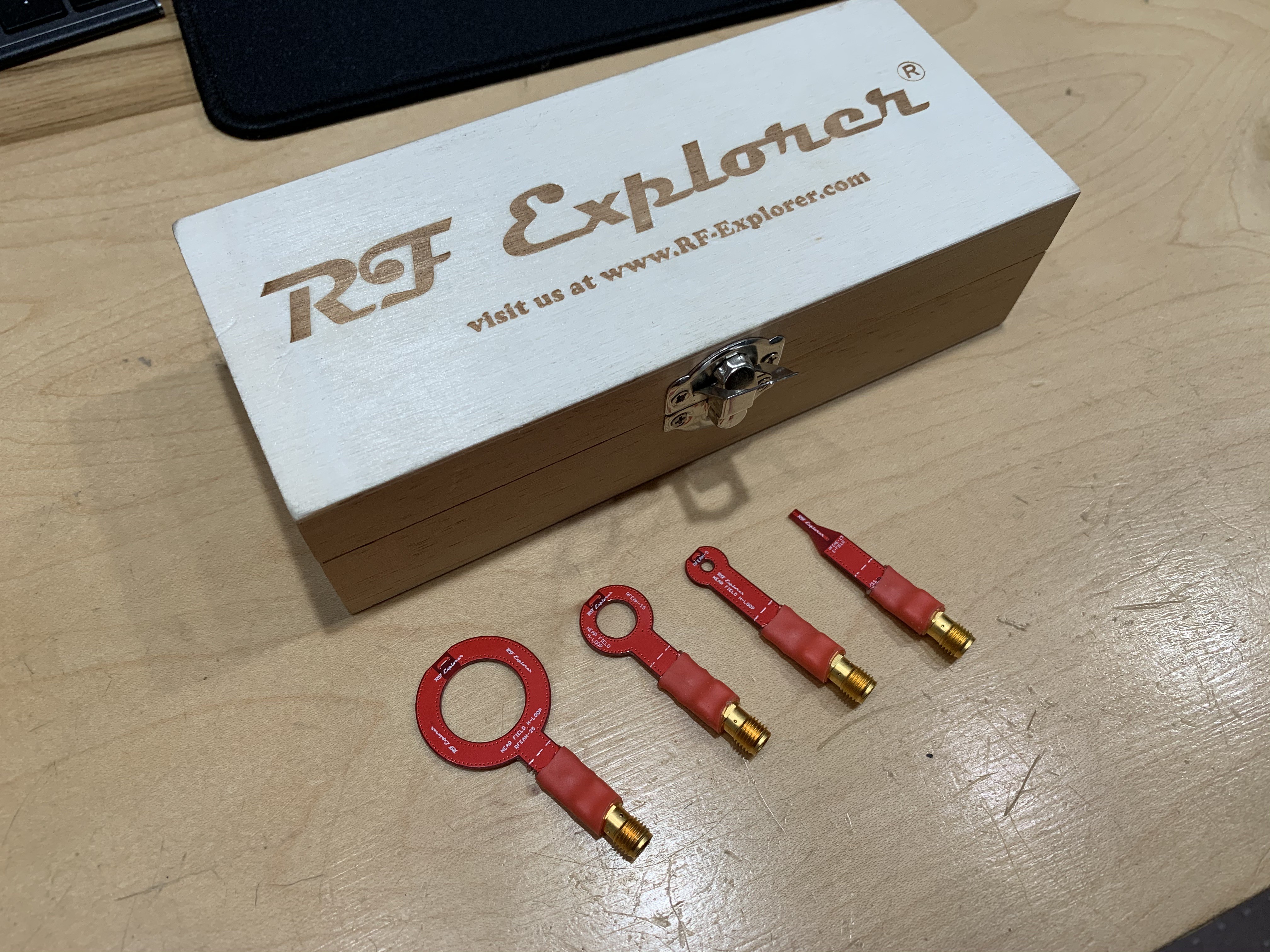
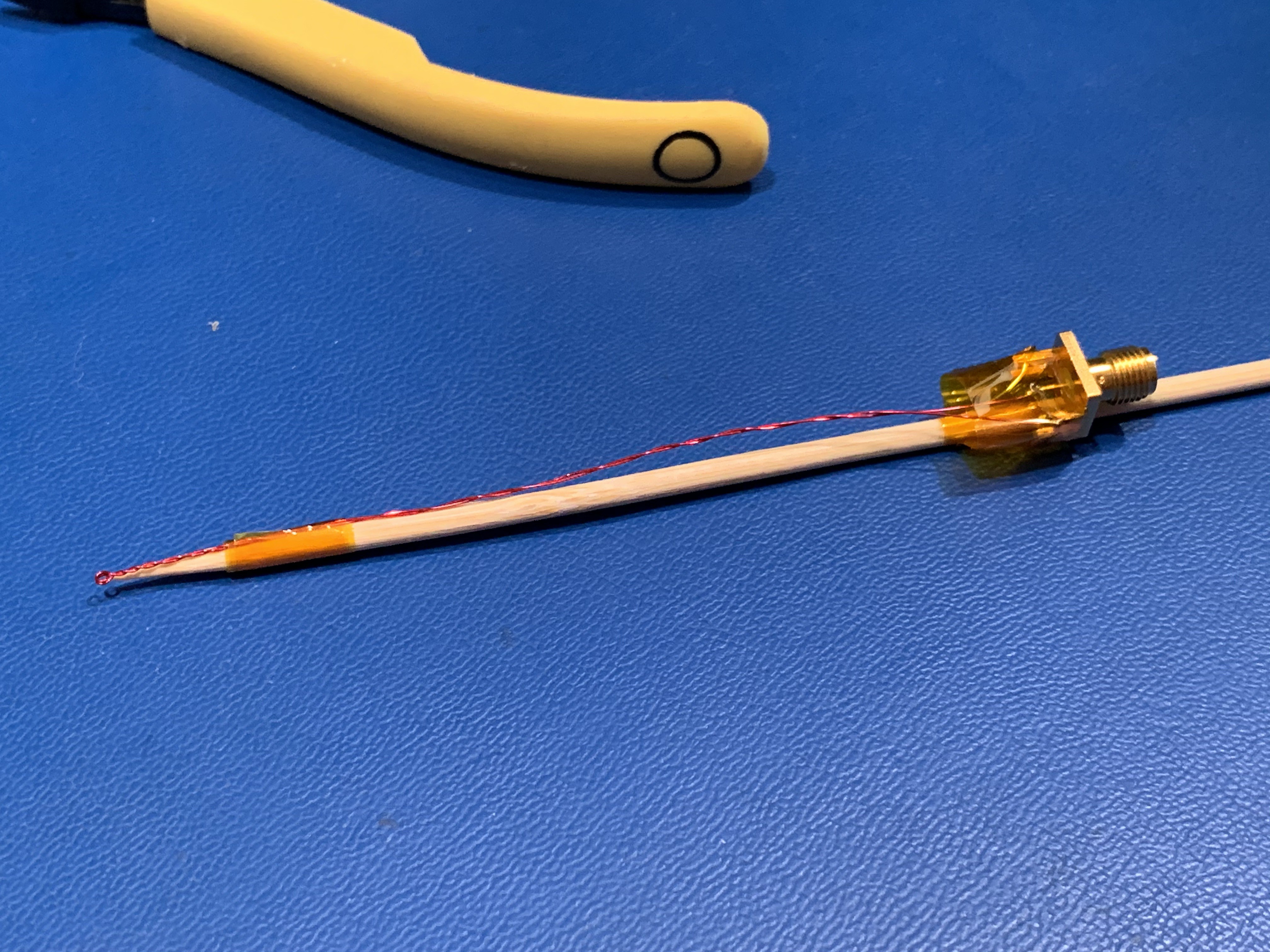
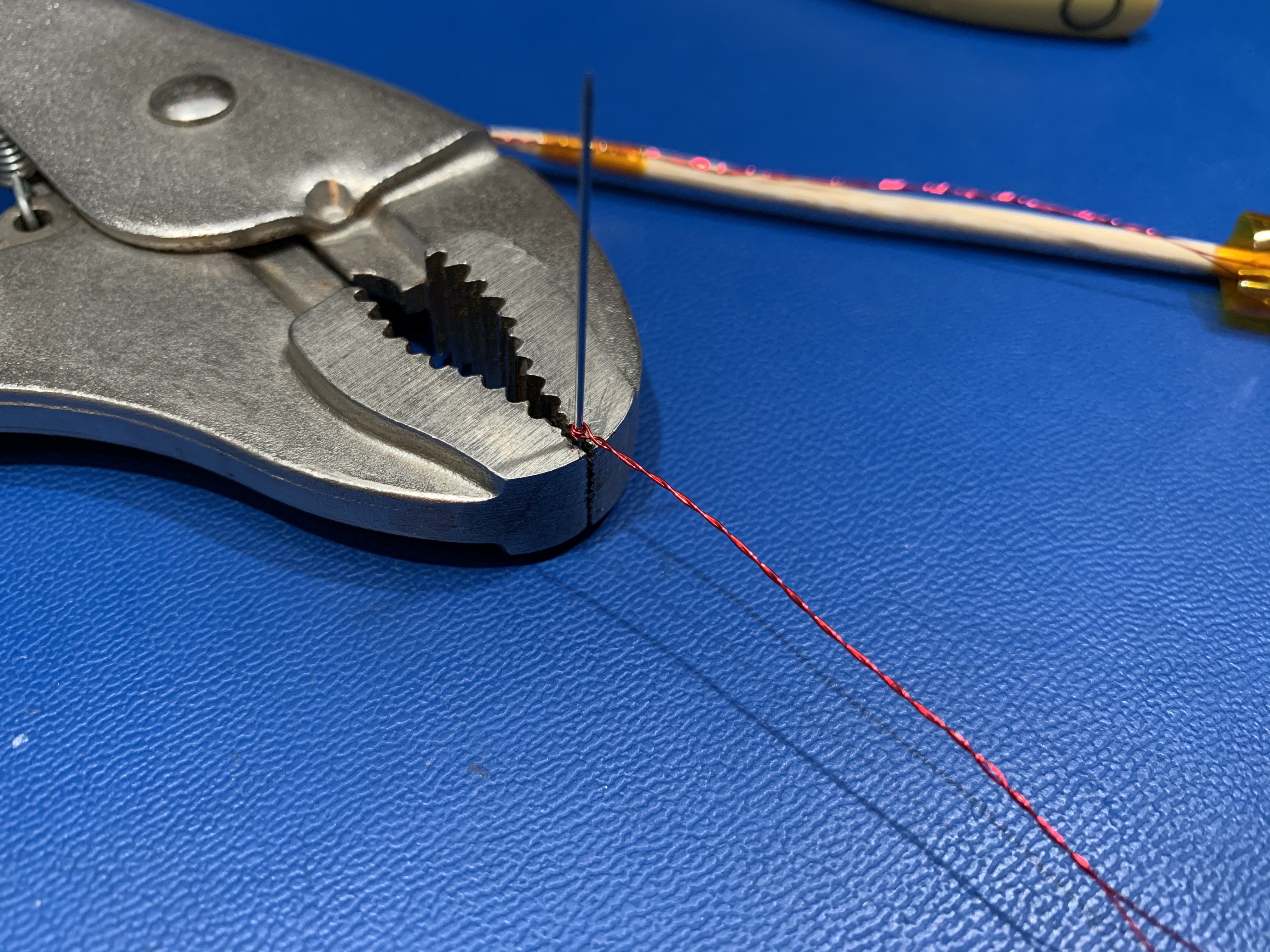
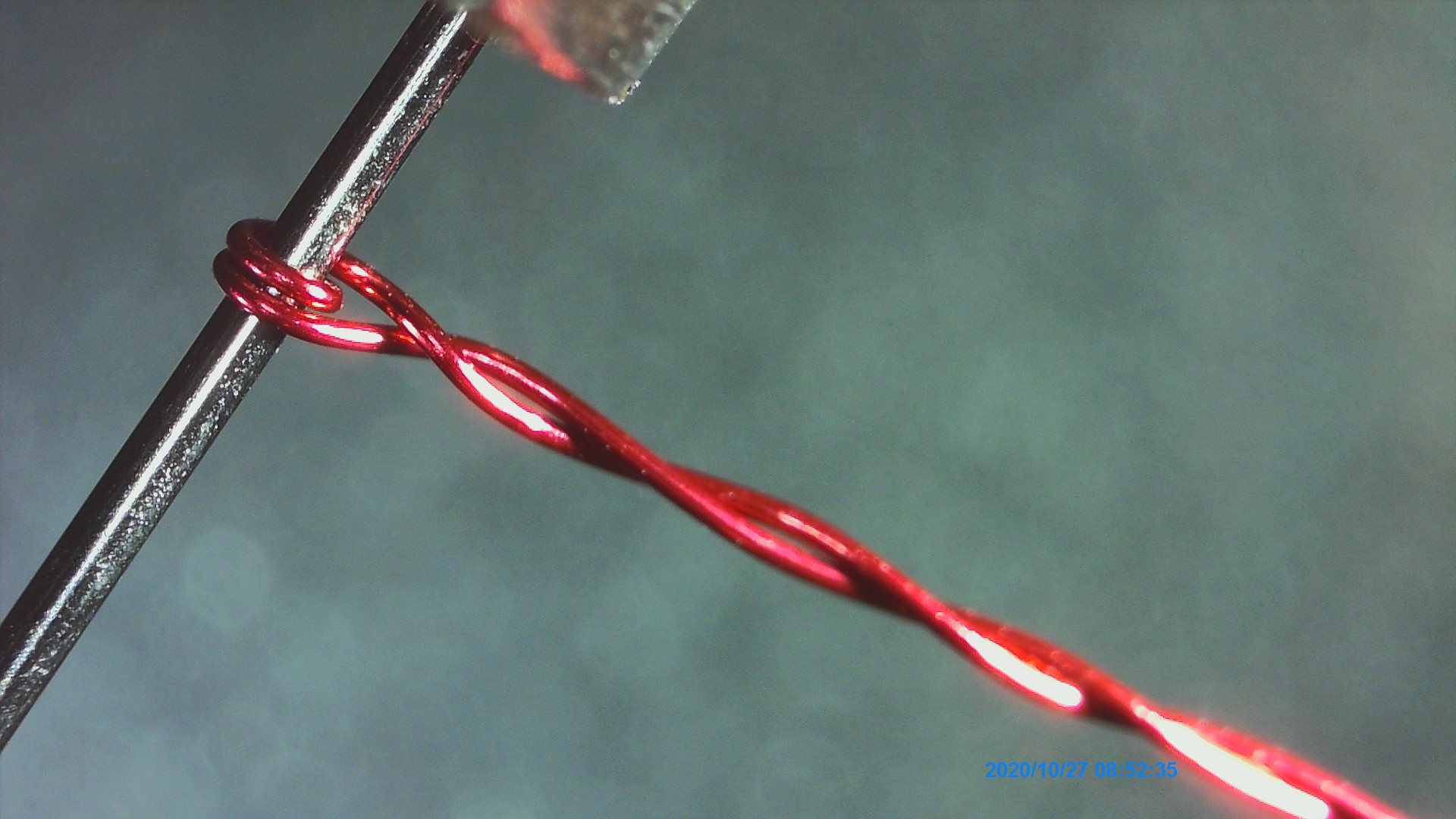
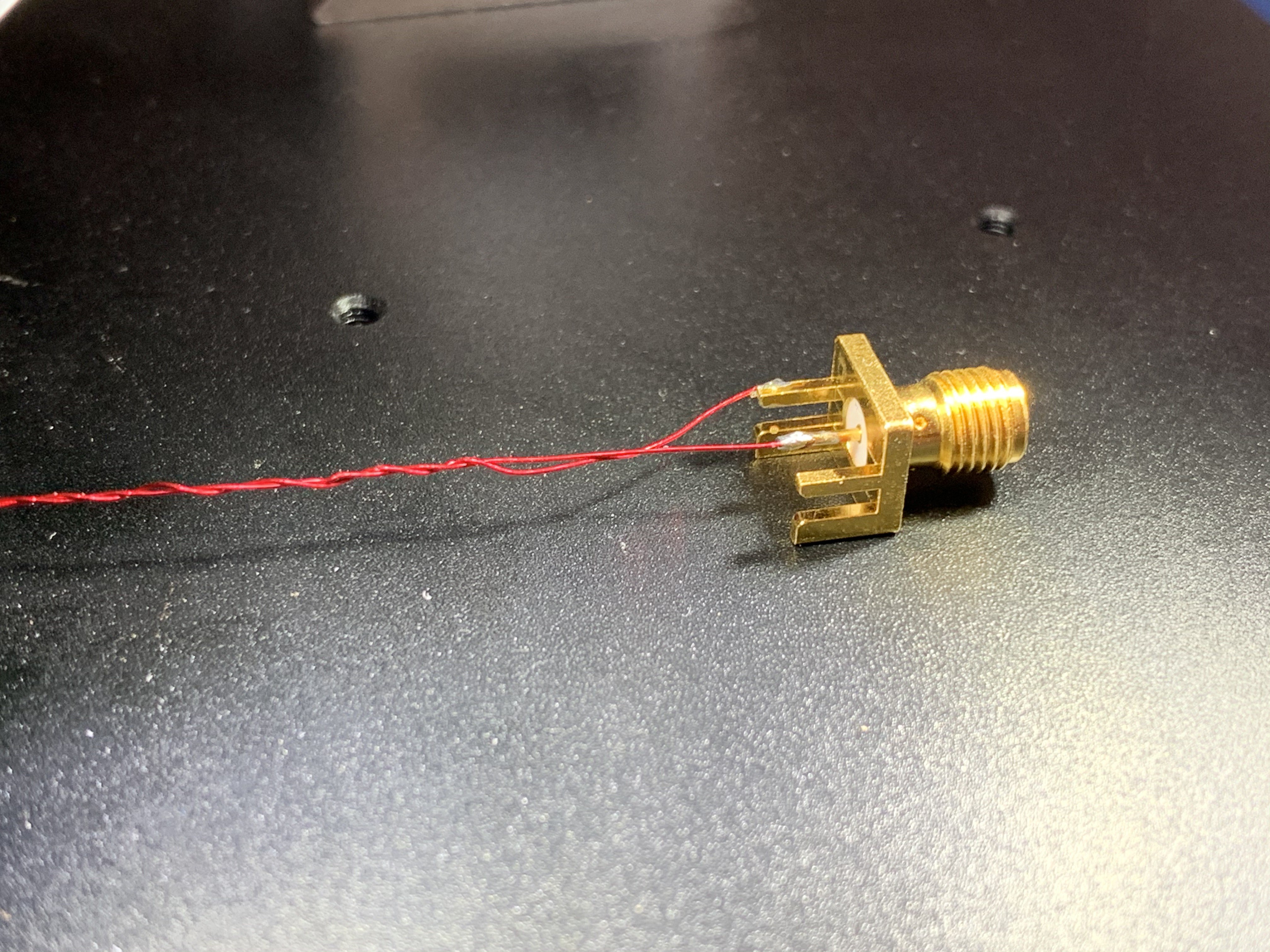
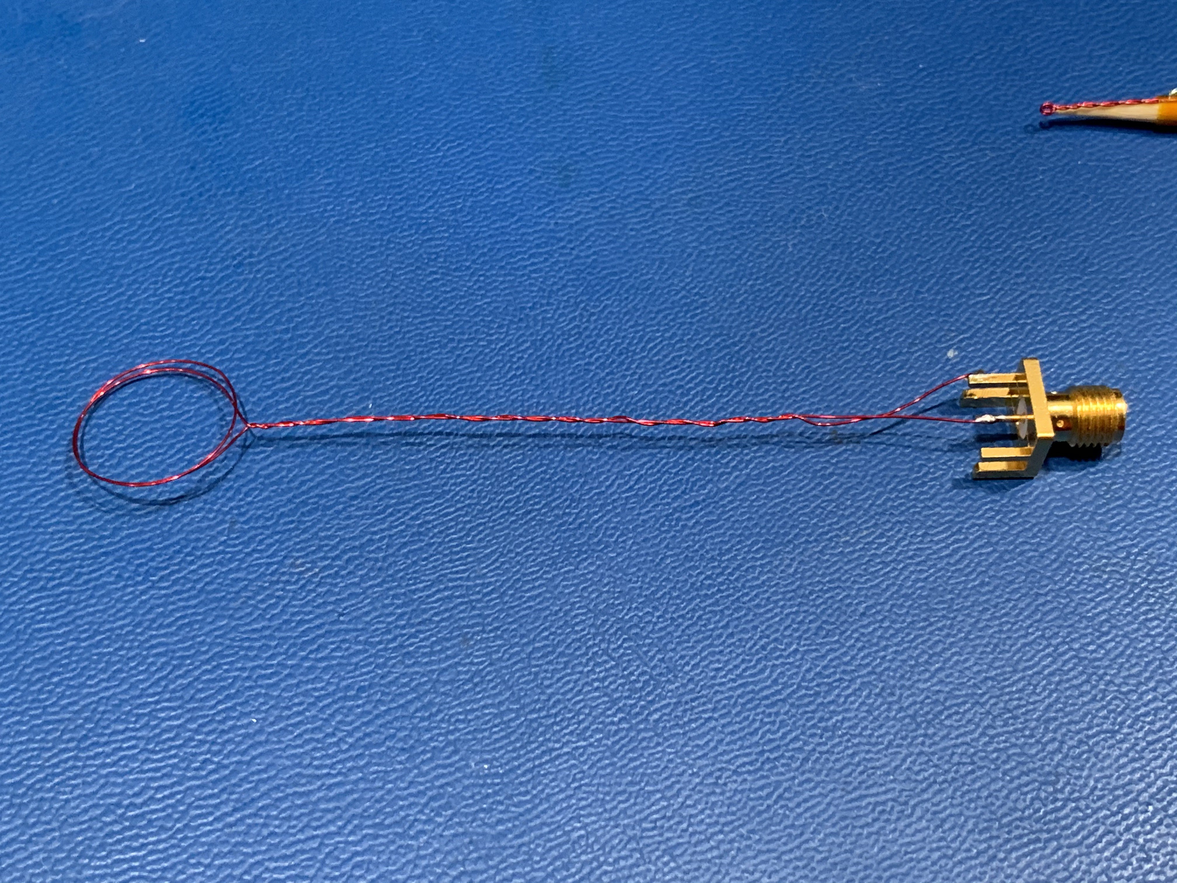
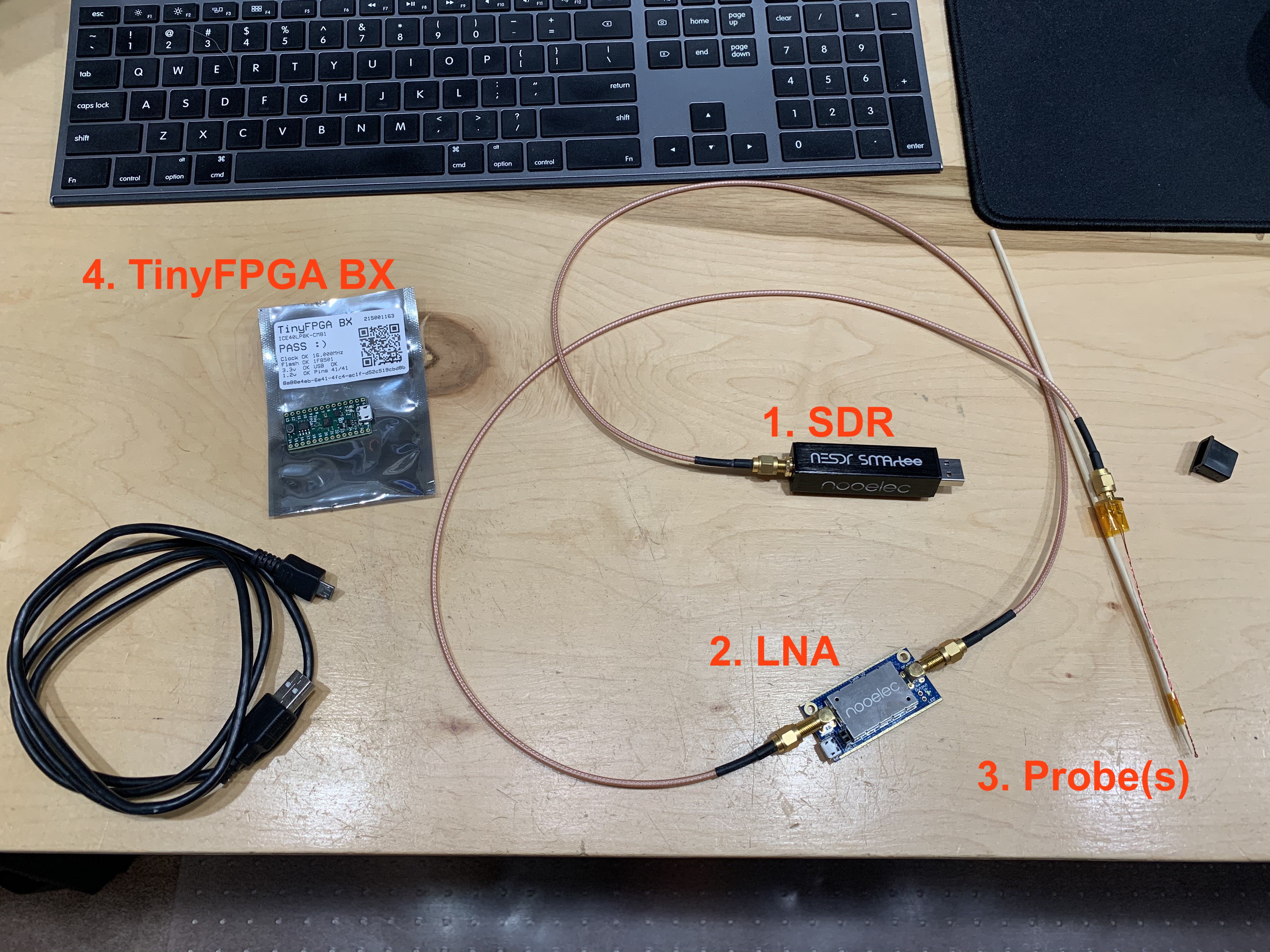
We'll work with tools set-up and fabrication (basically, make a couple of coils from magnet wire, soldered to a SMA header).

Instructor: Alex Whittemore

Alex is an electronic + prototype engineer who specializes in turning napkin sketches into proofs-of-concept with a path to production.

  • Software Setup Notes

    alexwhittemore11/07/2020 at 01:45 0 comments

    Setting up a SDR toolchain can be kind of a pain, in all my experience.

    Start Here

    The very baseline to start with is Nooelec's getting started guide for their RTL-SDRs. You should be able to set up CubicSDR with those instructions/driver installations, open it, and get a spectrum with your RTL-SDR.

    1. Launch CubicSDR
    2. File>SDR Devices and select RTL-SDR

    3. Click Start. 

    4. Set a center frequency of 100,000,000 Hz (100MHz), which is in the range of FM radio. Click on one of the obvious bright bands, and click FM top left to turn on FM audio demodulation. Listen to your favorite radio station!

    If you can get AT LEAST this far, you can participate in the workshop, so we're in good shape. 

    Set up your tools natively (Option 1)

    The next step beyond this is to try to get other tools set up. In particular, the tools I'm most interested in are QSpectrumAnalyzer and SDRAngel, if you want to try to set those up natively on your main system. If you can accomplish this, that would be best, but don't pull your hair out trying. In my experience, it might be very easy on one system and very impossible on another.

    Use a pre-built VM (Option 2)

    I've had good luck running DragonOS LTS in a vm, and it seems acceptably performant even in VirtualBox. Here's a copy of that. Username/password is "dragon/dragon." That said, I strongly recommend per notes below that you don't actually use VirtualBox if you can avoid it - import this VM into Parallels Desktop if you're on MacOS, or VMWare Workstation on Windows. Workstation I believe should be free, and Parallels you can try the trial.

    An older copy I installed of DragonOS Focal worked well too, but I set up Focal R7 today and had terrible luck with it, so I'm not sure what's up. I did upload a copy of that VM in VirtualBox format if you want to try it but I wouldn't recommend it. If you do, the username/password is "dragon/dragon," and I wouldn't click "update" when it prompts you until after you've had a chance to try tools. Maybe if you "update" stuff starts working correctly, I'm not sure.

    If you install DragonOS LTS yourself, be aware that it comes without rtl_power_fftw, which you'll have to install. Run the following in a terminal, and you'll be good to go:

    cd
    sudo apt-get install libfftw3-dev libtclap-dev librtlsdr-dev pkg-config
    git clone https://github.com/AD-Vega/rtl-power-fftw.git
    cd rtl-power-fftw/
    mkdir build
    cd build
    cmake ..
    make
    sudo make install

    General VM notes:

    • If USB doesn’t work, reboot the host. I know VirtualBox has to install some kernel drivers in MacOS for USB passthrough support, and you must restart before that will work.
    • If you’re getting weird behavior in the guest where you can’t click stuff, disable “mouse integration” and let your mouse be captured. There may be performance issues getting masked. I was running into a problem where I couldn't click anything reliably in the guest. When I disabled mouse integration, I realized the virtual mouse wasn't keeping up with the host system. A reboot fixed that (and disabling integration let me click things in the guest for a clean reboot).
    • VirtualBox kind of stinks. It can be tuned decently for a given host/guest combination, but I'm no expert. On MacOS, I suggest you use Parallels. On Windows, I suggest you use the free version of VMWare workstation. You can import the pre-built VMs above into either, or build them yourself.
    • If you want to import into Parallels, make sure you’ve configured networking first before installing parallels tools (Settings>hardware>+>network)

    Last but not least, TinyFPGA:

    Follow https://tinyfpga.com/bx/guide.html to install Atom and get a TinyFPGA toolchain set up.

    Being on Mac, my preference is for installing Python and other commandline-y things with Homebrew. You don't have to if you don't want to. The key takeaway here is that your python environment isn't really critical, it's just used during those instructions for installing tools. If you can...

    Read more »

View project log

  • 1
    Building your H-Field Probes

    For this project, we're going to focus on H-field probing, since it tends to offer excellent sensitivity and resolution, and building acceptable and useful H probes I think is easier than building acceptable E field probes.

    But wait, H field vs E field? Magnetic field vs Electric field. Where the electric field radiates out from relevant conductors and stubs, the H field radiates around them, just like a non-contact voltage tester senses the electric field near a live mains wire, while a current clamp senses the magnetic field around it due to current flow.

    In fact, that's an important distinction: E field probes sense AC voltage changes on a wire, where H field probes sense AC current flowing around a circuit. As it turns out, in very close to the circuit board, sensing AC currents gives you a much better sense of which devices and wires are responsible for which noise frequencies compared to sensing voltages. Case in point, have a look at this commercial set of near-field probes:

    You might notice that three of them are loops and only one is a straight stick: three are indeed H-probes, while only one is an E-field probe. In part, that's because different size H probes give different trades between spatial resolution and sensitivity: bigger is more sensitive, but smaller tells you more precisely where the signal is coming from in space. E-probes don't have quite the same trade. But it's also a reflection of how much you'll be using one vs the other in practice. In my experience, you'll spend more time swapping between the H probes to zero in on a particular area of the board, where you might use the E probe to find one trace vs another. And with the ultra-fine H probe we'll be making, you might not even need that.

    I'll skip for now the theory of how to make the perfect probes, because the probes below are MUCH simpler and still totally adequate for our purposes. I'll get into shielding a bit in the actual workshop, and you can experiment with it after the fact if you like - I certainly will.

    Building the "Fine" probe

    If you build only one probe for this workshop, it should look like this:

    It's basically one full turn (so, technically two turns) of fine-gauge enameled magnet wire (in my case, 30 gauge), soldered to an SMA connector to attach to our SDR. Obviously, ultra-fine magnet wire is pretty floppy, so I taped mine to a wooden skewer for stiffness and handling. Anything non-metallic and insulating will do just fine. I intended to build a plastic version by dipping my probe in 3D printer resin and curing over and over, like a candle, but didn't get around to it.

    The trickiest part is getting an ultra-fine loop on the end of the probe, which will result in very low sensitivity but extreme spatial resolution. We'll overcome the sensitivity issue with the LNA in our SDR signal path (see a later instructions post), and the resolution will give us single-trace accuracy looking for offending signals.

    To make mine, I used a sewing needle as a mandrel, though any similarly-fine wire should do. I imagine solid-core 22ga wire would work, if you're careful. Or a clipped LED lead, even better.

    This is what it looks like up close:

    With the loop made, twist the wires around each other as shown. The loop itself is SUPPOSED to be open, to "capture" the magnetic flux from your circuit like a net skimming a pool. On the other hand, since we ONLY want to know about the flux inside that little loop, we want to EXCLUDE any flux along the length of the handle wire. Twisting accomplishes that by 1) minimizing the area of any given loop, since the wires are very close to each other, and 2) flipping the polarity of adjacent loops. If the first parasitic loop has positive polarity with respect to the magnetic field, the second one will have negative polarity, cancelling any field that goes through both. It's a bit like building a transformer where half the secondary is wound one way, and the other half is wound the other way: you'd always get zero volts out. Actually, it's literally exactly that.

    Finally, solder on the SMA connector. Polarity doesn't matter, since we're only interested in amplitude of an AC signal.

    Ok FINALLY FINALLY, attach the skewer or whatever other handle you come up with.

    Bonus: Building the "Medium" probe

    I told you that you only NEED this super fine probe for the workshop, but there's a little more to see if you have a range of probes. I built this other probe exactly the same way as the one above, but using a "AA" battery as a mandrel instead of a sewing needle. I encourage you to do the same, and if you've got extra SMA connectors, build a few of different sizes. Bigger than 2cm isn't super useful, and much smaller than what we built above might not be either, so probably stick inside that range.

  • 2
    Setting up your workbench

    Before we start the workshop, this is what your workbench should look like:

    1. SDR

    I selected the Nooelec NESDR SMArtee for a couple reasons: 1) the RTL-SDR system is widely-supported and easy to use 2) it's as cheap as SDR gets 3) the SMArtee has a bias tee built in to power our specific LNA without any external shopping list items. 

    The critical pieces here, if you don't have the same SDR, are that it can receive as low as 50MHz (our signal of interest), and that you have a tool chain set up to actually run it (since this is the absolute hardest part of ANY SDR activity). 

    2. LNA

    The Low Noise Amplifier is a critical component of our signal chain because the probes we're using are extremely low-impedance and low-sensitivity. The biggest issue with amplifiers in general is that they tend not to be perfectly flat across their whole frequency range, and therefore they introduce substantial measurement error. Luckily, in our case, we don't really care about that, since we're not trying to measure absolute signal strength. We JUST need to boost the microscopic signal up to the point where we can see it with the SDR, so that we know where it's coming from on the board by virtue of where our probe is when it shows up.

    I chose the Nooelec LaNA again because it happens to play nicely with the SMArtee. LNAs are basically just common emitter amplifiers powered by a DC offset on their output. Since the entire RF signal chain is AC, you can isolate DC offsets anywhere you like by simply adding a series capacitor. Many LNAs have such caps on their output so they must be powered by some alternative source. The LaNA does not, AND it has a very low supply voltage requirement that's satisfied by the SMArtee's relatively low 4.5V bias voltage. 

    In theory, the gain of the LaNA here is a bit lower than you can get with some cheaper DC-powered LNAs (that I use and like), but in practice I didn't actually notice a large difference. Either is definitely sufficient for our workshop.

    Important LNA/bias tee notes

    There are a couple important things here.

    1) Our low-impedance probe looks like a short at DC

    2) Our SMArtee SDR has a 4.5V DC bias on the input that can't be disabled

    3) Our LaNA is nearly bulletproof

    The SMArtee puts out 4.5V dc, and while it has short-circuit protection, you should NOT short it for very long. That is to say, while it's tempting to try the setup WITHOUT the LNA just to see whether the signals are still detectable, you should not do this with this particular SDR, unless you have a DC blocking capacitor between the antenna and the SDR. You can do this with E-field probes, which aren't electrical shorts at DC, but not our naive H probes.

    On the other hand, the LaNA is surprisingly robust. Given that it's compatible with powering via both bias tee and DC input, you might worry like me that using both at once would be a big no, shorting the DC supply to the RF output. Not so. The LaNA has a lot going on inside, including power isolation so that you can use external power even with a receiver that has permanently-on bias tee.

    Now, you shouldn't NEED to do this if you're using the setup above, but in my case it was useful for switching between two SDRs for comparison, one of which didn't have a bias tee, while powering the LaNA from USB the entire time.

    Anyway, long story short, don't connect our H probe to the SDR without the LNA in between.

    3. Probes

    There's not much to say here if you read the previous instruction step where we built the probes, other than the more the merrier. I'll personally be demoing two sets on top of the ones we built, including the RF Explorer budget probes, and the Rhode & Schwarz HZ-15 not-at-all-budget probes a client of mine happens to be renting right now. Luckily, it turns out, there's virtually no difference in performance, only build quality. 

    4. TinyFPGA Bx (And Micro-USB cable!) (And other boards!)

    Lastly, we have to have something to measure. I've chosen the TinyFPGA Bx to be our device under test (DUT), because it's the cheapest way I know of to generate 50MHz noise on a programmable pin. However, I strongly encourage you to show up to the workshop with some other boards you might have laying around! The TinyFPGA is useful here because it gives us all a common reference to work on, but when you get in close to any board, it'll have all sorts of noise to explore. Grab an Arduino Uno and see if you can measure harmonics of the 16MHz crystal (16 is too low for the RTL-SDR, but 32 isn't). Or maybe an ARM arduino will show you its core clock around the chip. 

    The technique we'll be focused on depends on knowing what signal we're looking for first, and trying to figure out what's making it. But with patience, this can be done in reverse as well, looking for a signal we suspect might exist, or using a large probe to look across the entire spectrum at once farther away from the board. Making your own educated guesses and confirming them with a unknown DUT, like "I see a crystal, I bet I'll see X MHz noise" is just as educational!

  • 3
    Setting up the software

    We'll need two main software toolchains to get up and running: one for the SDR, and one for the TinyFPGA.

    Setting up the SDR software

    On the SDR side, we'll be using a couple of utilities: QSpectrumAnalyzer (https://github.com/xmikos/qspectrumanalyzer) and SDRAngel (https://github.com/f4exb/sdrangel)

    QSpectrumAnalyzer is great because it lets us use our SDR like a traditional swept spectrum analyzer, capturing very wide bandwidth in a single sample. The disadvantage is that such a capture takes a long time, so there's a good chance that your signal of interest doesn't happen to be loud or "on" when the analyzer is sweeping that part of the range. The advantage is that you can see EVERYTHING all at once, rather than manually tuning this 2MHz range, then that 2MHz, then the next, and so on. 

    SDRAngel is useful because, for a frequency range narrower than the real-time bandwidth of your SDR device, SDRAngel has a view very closely approximating a real-time spectrum analyzer (RSA). Luckily, I have one of those on hand to show you a comparison. With the very limited bandwidth of the RTL-SDR, this is pretty limiting in terms of what we can accomplish, but it offers a lot of information in one view when analyzing a signal whose frequency we already know. 

    Like I said before, setting up SDR software is very much, in my experience, the most painful part of the technology. If your computer is at all capable, I STRONGLY encourage you to download VirtualBox and set up DragonOS, which is a project to build an out-of-the-box SDR environment with broad hardware and preinstalled software support, with minimum configuration hassle. It comes in a couple flavors including "DragonOS Focal" (https://sourceforge.net/projects/dragonos-focal/) which seems to be the most recent development, and "DragonOS LTS" (https://sourceforge.net/projects/dragonos-lts/) which is what I've personally used. There are also a lot of videos on YouTube made by the creator demoing various devices and software, to give you an idea of how to pilot many of those combinations, which I've found super useful. 

    Long story short, if you can download and install DragonOS (I'll personally test Focal ASAP), connect your SDR to it, and get a spectrum to show up in QSpectrumAnalyzer and SDRAngel, you're in good shape for the workshop.

    If your machine isn't quite powerful enough to run a VM, you CAN install both programs on your native OS. I encourage you to get started trying ASAP.

    Setting up the TinyFPGA toolchain

    Follow this guide to set up the TinyFPGA toolchain with the Atom editor: https://tinyfpga.com/bx/guide.html

    If you can flash the test program and make your LED blink, that's a great start!

    I'll try to have the ACTUAL workshop firmware and flashing instructions ASAP :)

View all 3 instructions

Enjoy this project?

Share

Discussions

Marc [LAN|WAN]dolt jun [מאַרך لاندولت] wrote 11/14/2020 at 02:33 point

little question, has anyone thought of using the concept of #Spectre / #Meltdown in other HW (HD's,SoudCard...) to load a data values in "REGISTERs" that is prone to #TEMPEST attacks?

The LED for Power/HardDisk Activity/... would be driven by a "Industrial Driver for eg. 4-20mA", therefore more prone to #TEMPEST #Attacks than eg. a register in a CPU, HardDisk, VideoCard...

Most Stupid Idea would be to just transmitt the keylogged root password of the system...

Sencerely your #HackersCardgame.ch

  Are you sure? yes | no

Carl Hage wrote 11/07/2020 at 02:42 point

I noticed the NooElec install instructions for ubuntu didn't indicate how to unload the active default driver modules after setting the blacklist-dvb. I used lsmod | grep dvb and lsmod |grep rtl to find modules. You can't remove modules until others it uses are unloaded.  The left side of lsmod is the module, and right side, list of dependencies. So I used "sudo modprobe -r dvb_usb_rtl28xxu dvb_usb_v2 dvb_core" but core was in use, so I did sudo modprobe -r rtl2832; sudo modprobe -r dvb_core. When I replugged the SDR then everything worked, and rtl_test responded. I guess I could have rebooted.

  Are you sure? yes | no

alexwhittemore wrote 10/16/2020 at 19:16 point

Don't worry everyone, working on background and prep info to post here ASAP, including everything you'll need to get together and set up pre-workshop, and backup plans if you can't!

  Are you sure? yes | no

Similar Projects

Does this project spark your interest?

Become a member to follow this project and never miss any updates