 Mirel Paun
The construction and software files contain the complete information for building the project.
0%
0%
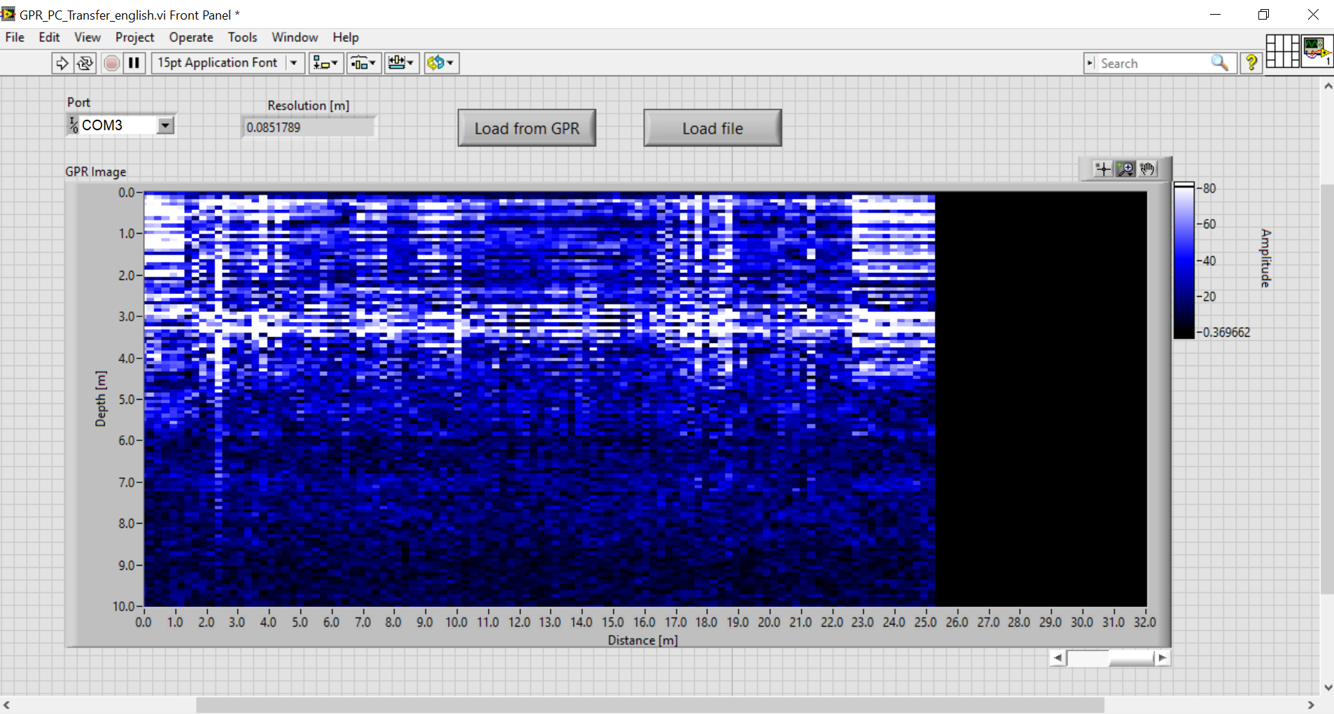
GPRino
Ground Penetrating Radar using Arduino
Become a Hackaday.io member
Already have an account? Log in.
Just one more thing
To make the experience fit your profile, pick a username and tell us what interests you.
Pick an awesome username
hackaday.io/
Your profile's URL: hackaday.io/username. Max 25 alphanumeric characters.
Pick a few interests
Projects that share your interests
People that share your interests


 Abid Jamal
 engineerkid1
 CiferTech
 Jean Noel
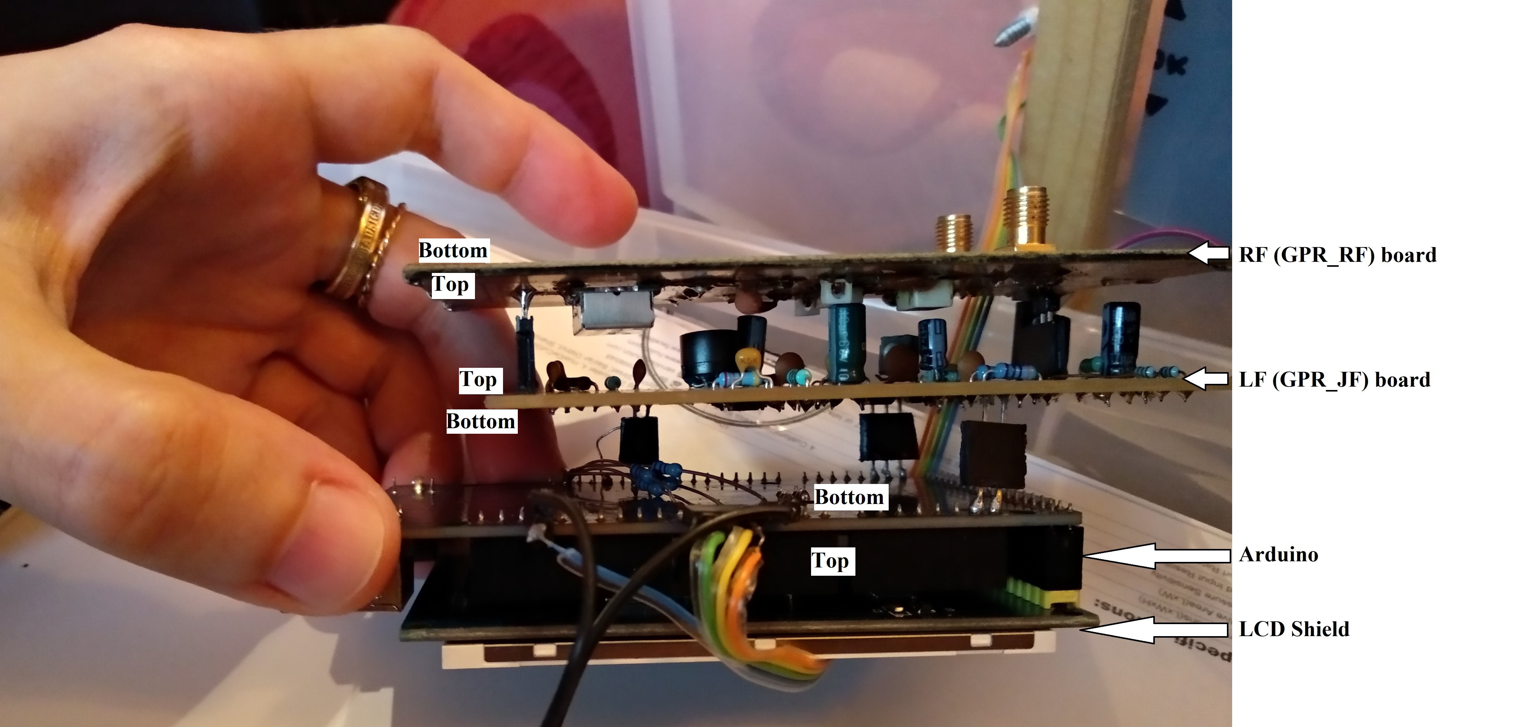
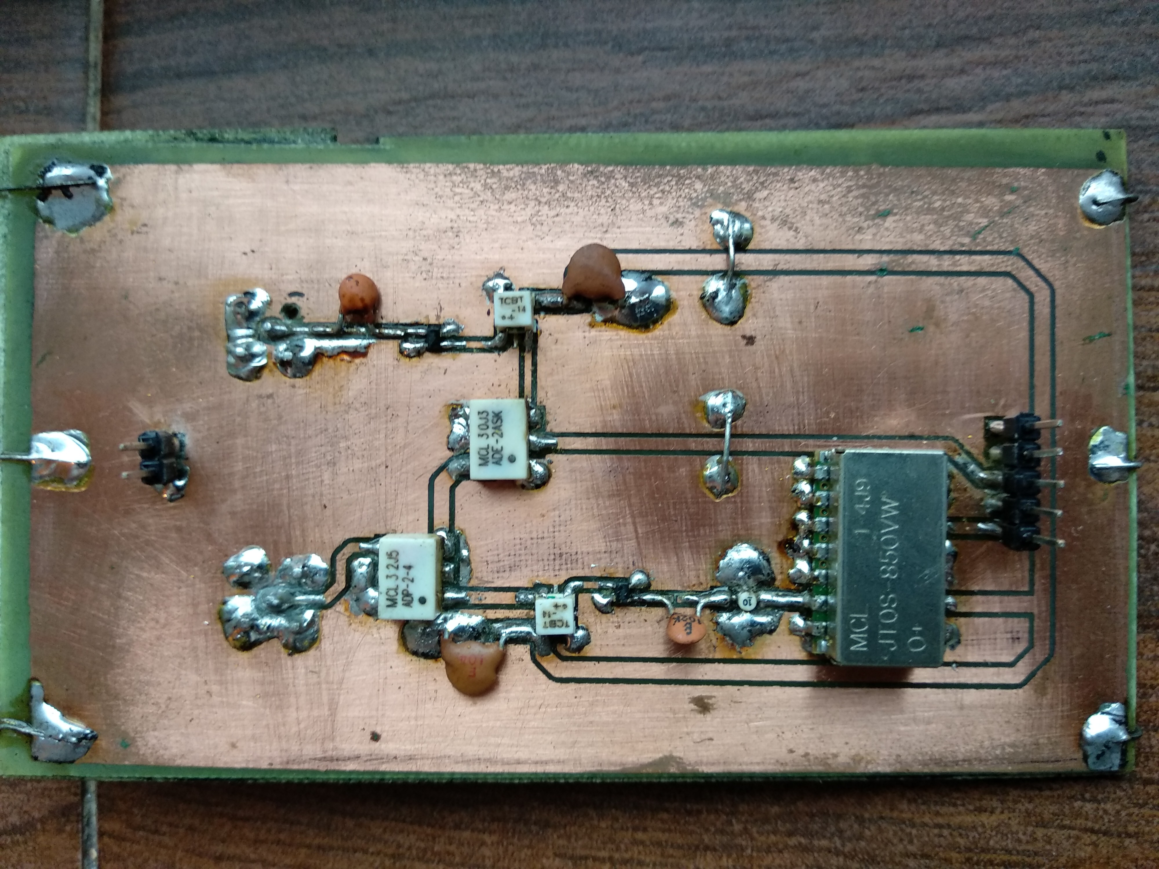
Good evening, I noticed in the diagram the components LMV772 and MCP4725, in the photos the 772 has 6 pins but they only exist at 8 pins.. while the MCP4725 has 8 pins in the photo but I can only find them at 6 pins.. what was mounted on the card instead of the ones in the diagram? can someone help me? what did you mount on the card? do you have any alternatives for me? Thank you.