 Ken Yap
It started when I looked at an integrated LED display in my junk^Wspares box. This came from an old 386/486 era PC and could display the clock frequency up to 99 MHz. As installed it displayed only two speeds, normal and turbo, selected by a push button switch. A quirk was that the digits were yellow but the MHz (which would have been permanently lit) were in red. I liked the dual colours.
I wondered if I could make a clock display out of this. With only two digits I would have to multiplex hours and minutes. It occurred to me that I could display 12:34 as 12 H, followed by 34M.
There was another quirk and that was the MHz part only had 7 "segments". The vertical bars of the M were a segment each. The v in the middle was another segment. Similarly for the vertical bars of the H. However the middle bar was joined with the top of the z, and the final segment was the < of the bottom of the z. This meant that I would always have a "hyphen" after the H, so 12:34 would be displayed as 12 H-, then 34M. I will call this a feature. 😉
Each of the MHz "segments" comprised two red LEDs in series, for a forward voltage of about 3.6 V whereas the yellow segments were single diodes with a 1.9 V forward voltage. Obviously such a display was a custom made part for the PC manufacturer. That's why you will not be able to reproduce this clock, unless you have rescued an identical display. But if you desire you can modify the software (mostly take out the code that handles the hour/min multiplexing) to drive a conventional 4 digit display.
Goals
I made this clock to tackle these challenges:
- Program the STM8, in particular the STM8S103F6, in C using SDCC and a ported Standard Peripherals Library
- Multiplex hours and minutes on 2 digits
Wiring
As I have only one display, it would be a waste to get at least 5 fabricated by a PCB house, and there would be a long shipping delay, unless I pay even more for expedited shipping. So I wired up the project on a perfboard. It's ugly, and even worse on the other side so I won't show that.
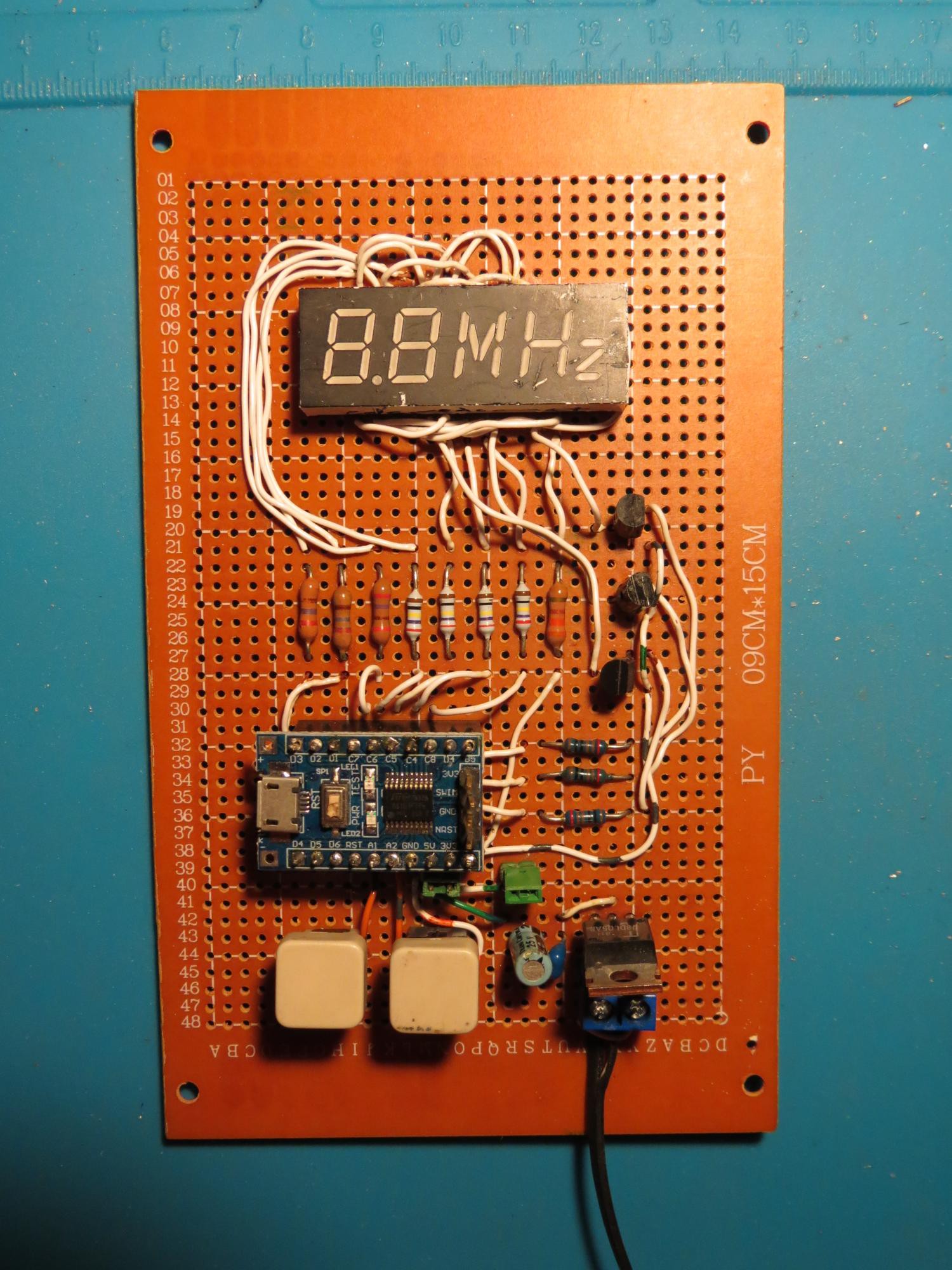
By the way the buttons are also recycled from PCs; they used to be reset buttons. The power supply is a recycled Nokia charger, feeding a 7805 voltage regulator.
There were quite a few joints to solder, that's what happens when you turn a non-multiplexed display into a multiplexed one, so I was glad I was only making one board. Testing showed besides a handful of short circuits and dry joints, a couple of boo-boos: I thought the cathode driver transistors had an EBC footprint but they were ECB. Duh. So a little rerouting of the wires. Another small rerouting was needed because I had transposed two pins of the display, swapping segments b and g of the second digit.
But eventually it passed and I connected it up to an Arduino to display a periodic pattern.
Software
SDCC supports the stm8 architecture. I needed definitions for the STM8 resources such as the registers. I wondered why they did not come with SDCC. To cut short a long adventure down a rabbit hole, it turns out that initially ST did not provide include files and libraries under a suitable license for open source. Eventually they realised their mistake but by then workarounds were swirling around the Internet. However there has been a port of the official Standard Peripherals Library to SDCC. You can read the instructions for building SPL on Linux to get the include files and the library. The advantages of using these includes and library are that: the code becomes more self-documenting, if prolix; there is some error checking of usage; and the SPL for STM32 is similar when you want to reuse the knowledge.
I also used Adam Dunkels' Protothreads for the switch handling.
Firmware for a MCU based clock has several subsystems. I indicate the C source file that handles each subsystem. It may be useful to refer to the source code.
- The timekeeping code (tod.c) which counts subseconds, seconds, minutes and hours
- The periodic timer (tick.c) which handles the digit scanning and button polling
- The display (display.c) which takes a time and converts it to an array of 7-segment bytes to send to the output port.
- The button handler (button.c) which reads the state of the buttons
- A system module (mcu.c) that sets the initial configuration
- The main program (clock.c) that binds all the modules together
Timer1 is used for timekeeping as it is more capable and has advanced options I will use later. The CPU 16 MHz clock is divided down to 64 Hz, which then increments a time of day structure containing counters.
Timer4 is used for the tick generator, running at 500 Hz, which is used to scan the digits and poll the buttons.
The display strategy is simple for multiplexed displays. There is an array of bytes that represents the segments for each of the digits. The code turns on each digit and the appropriate segments in order. A font table translates from the binary numbers in the hours and minutes counters to the 7 segment patterns needed. Note that the arrays need to be updated only when a visible digit changes, so not every second, but every minute, and also when setting the clock.
Note that unlike more basic MCUs, the segment pins are taken from a combination of ports as none of them expose all 8 bits in the TSSOP-20 package. This means I can't use byte operations to operate on all segments in one go, but have to do it one segment at a time in a loop. But the MCU is fast enough that the overhead is negligible compared to the tick period.
The tick also scans the buttons each time around the loop and updates the Protothreads state machine for button actions. A single press increments once. Holding down the button will after a short delay, autorepeat increment at 4 times per second.
The system module initialises the desired configuration of the MCU. In particular I use the built-in 16 MHz RC clock.
The main program calls the initialisation routine of each of the above modules, then enters the tick loop.
Modifications for multiplexing hours and minutes
To handle multiplexing hours and minutes I have 2 display arrays instead of one. The first holds the two 7-segment digis of the hour, plus a constant 3rd byte representing the segments for H-. The second holds the two 7-segment digits of the minutes, plus a constant 3rd byte representing the segments for M.
In the tick loop, whenever the second counter changes, it is tested. If the modulo after division by 5 is 0 to 2, the display pointer is to the minutes array, otherwise for 3 and 4, it points to the hours array. The result is that for a time of say 12:34, it displays 12 H- for two seconds, then 34M for three seconds.
I need to suspend this multiplexing when setting the time. When the hours increment button is pressed, the display is hours only until the button is released. Similarly for the minutes button. A small point is that when the minutes are advanced, the seconds are set to zero. This allows synchronisation of the clock with another clock by setting the time to the same minute and then incrementing the minutes with a quick jab when the seconds roll over.
Another small tweak I have applied is to give the red "digit" twice the amount of digit time to compensate for the lower LED current. So the yellow digits are run at 25% duty cycle and the red "digit" is run at 50% duty cycle.
Using a standard 4 digit display
For people thinking of modifying my code to drive a standard 4 digit display, here are my untested surmises about what would need to be done.
On the hardware side, you would need an extra port pin to drive the 4th digit. D1 is the first logical candidate, but remember that on the breakout board I used, it is also the SWIM pin for flashing the executable image. So you would need a jumper that can be removed when flashing and put back for operation. Another possibility is to not have a colon and use A3 for the 4th digit. Note that B4 and B5 can't be used as is because they are open drain pins for I2C and would require adding a pull-up resistor to turn on the cathode drive transistor. The other problem is B5 drives the blinky LED. I suppose you could make B5 the 4th digit drive, then the LED would provide the cathode drive transistor current. In which case B5 glowing would indicate that the clock is running.
On the software side, you would substitute a single 4 byte display array for the two separate 3 byte arrays, and there would be no need for switching the pointer between the arrays. Naturally the number of digits would increase to 4 but this is handled by the hash define that uses the sizeof operator when you add one more element to the digit port-pin declarations. Oh and you can rid of the tweak to give the red "digit" extra scan time, since your digits are all identical.
Feel free to fork my repository if you want to publish your changes. My code is free to use under MIT license.
Tweaking the clock source
Tweaking the clock rate uses a Numerically Controlled Oscillator, a technique which was brought to my attention by @K. C. Lee and used in his clock, which also uses a STM8.
Let's make the example concrete by looking at the changes to tod.c. Timer1 is still configured to generate 64 interrupts/second. However now the subsecond counter instead of counting to 64, counts to 32. We create an accumulator called DDS_Accum, which is incremented by (2^23 + adjustment) every interrupt. When DDS_Accum exceeds 2^24, almost always every 2 interrupts, the subsecond counter is incremented, and 2^24 subtracted from DDS_Accum. The choice of a power of 2 for the overflow and the subtraction is so that we can do them by bit testing and bit masking respectively, so the machine code is more efficient.
Now observe the effect adjustment has on the accumulation. If it is zero, then the scheme operates as a simple divide by two. If it is negative, every so often the accumulation will not exceed the limit, and the increment to the subsecond counter will not happen; a tick is dropped so to speak. Conversely if it is positive, every so often the accumulation will exceed the limit twice in a row, so you get an extra tick. The effect of a negative adjustment is to slow the clock and of a positive adjustment to speed the clock. The fractional adjustment is given by adjustment/2^23. As this is happening before the seconds counter, we don't notice these little jogs, and even less so as the lowest display is minutes.
This can be generalised to (timer interrupt/subsecond rate) factors that are not 2, but there is no need for larger factors.
Result
I put some black tape over the blue power LED which is insanely bright otherwise it will overpower the brightness of the digits and make the clock unusable in a bedroom at night.
I also used a black marker to conceal some scratches on the black face of the LED display.