Close
0%
0%

XJW01 Bench LCR Meter

Making a bench LCR meter out of a cheap Chinese kit

Similar projects worth following
How to make a bench LCR meter out of a cheap DIY kit

Overview

The system is built around a XJW01 LCR kit. The kit comes half-assembled. You will have to solder in a bunch of through hole components. However, then you're just left with two circuit boards.


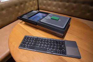
To make it into a nice unit for on my bench, I've designed and printed a case that can hold a power supply and aligns the display and keys for easy usage.

I've used a linear power supply. I'm not sure if that's necessary with this instrument, but hey, why not, we can at least pretend we're doing metrology-grade stuff :D The fuse holder and switch are in-line with the power input for the supply. If you're in a 110-120V region, make sure that you order a 120V rated transformer.

For attaching the display and keyboard section, I've used the standard Arduino ribbon cable. It's a bit of a hassle to solder in, so you might want to use a connector for this. Of course I've added plenty of hot glue for strain relief.


At the bottom of the case, there are recesses for rubber feet, so the thing won't slide around.

LCRCase - FrontPlate(1).stl

Front plate STL file

stl-binary - 1.37 MB - 10/30/2020 at 17:16

Download

LCRCase - BottomPart(1).stl

Bottom part of case STL file

stl-binary - 1.45 MB - 10/30/2020 at 17:16

Download

LCRCase - TopPart(2).stl

Top part of case STL file

stl-binary - 713.36 kB - 10/30/2020 at 17:16

Download

LCRCase - BackPlate(2).stl

Back plate STL file

stl-binary - 396.66 kB - 10/30/2020 at 17:16

Download

View all 7 components

  • 1
    Assemble the XJW01 kit

    The XJW01 kit comes with a bunch of resistors and capacitors that need to be soldered in. Also note that the kit comes with a small ziplock bag with 'calibration resistors'. You won't have to use these in the build, that will come later when calibrating.

    Use ribbon cable to connect the display and keypad to the main circuit board. I've used around 15 cm of ribbon cable for the display and around 10 for the keypad.

    After you're done, you can test the kit with a 12V bench power supply to make sure it turns on. Don't worry too much about the values it shows, it might not be calibrated properly.

  • 2
    Print the case parts

    Print the attached case parts. I've used 0.2mm layer height with a 0.4mm nozzle with 35% infill, printing PLA. The pieces can all be printed flat on the bed, but you might need to rotate them in your slicer.

  • 3
    Calibrate the meter

    It's time for calibration. It's not a super-obvious procedure, but it is fairly easy.

    First, measure the included resistors as accurately as possible. There should be a 40R, 1K, 3K, 9K, 10K and 100K resistors. Go nuts with 50 power line cycles, averaging, 6,5 digits, 4-wire measurements and all that. We will use the measurements you've done to calibrate the meter to.

    Once you've measured the resistors to an accurately enough degree, it's time to start the calibration procedure:

    1. Turn the unit on
    2. Perform a short test lead calibration. Clamp the Kelvin clips together and press the "Zero" button
    3. Perform an open test lead calibration. Disconnect the kelvin clips and press the "Zero" button
    4. Hold down MENU for approximately 3 seconds, this will bring up the options menu
    5. Press RNG to enter calibration mode, the display should now show "Z0"
    6. For the calibration, we will adjust the instrument to exactly match the previously measured resistor values (as well as some other parameters). Use the CLR (up) and SP/ESR buttons (down) to adjust the values. Use FREQ to go to the next parameter and QTY to go back.
    7. Set the values of the different parameters as follows:
    StepTarget ValueNotes
    Z0Z=0Short the Kelvin clips
    Z1Z=0Short the Kelvin clips
    Z2Z=0Short the Kelvin clips
    R140R resistor
    Connect the resistor and try to match what you previously measured with your multimeter
    R1Xθ=0Leave the resistor connected
    R21K resistor
    Connect the resistor and try to match what you previously measured with your multimeter
    R2Xθ=0Leave the resistor connected
    R310K resistorConnect the resistor and try to match what you previously measured with your multimeter
    R3X0 pFLeave the resistor connected
    R4100K resistor
    Connect the resistor and try to match what you previously measured with your multimeter
    R4b100K resistor
    Connect the resistor and try to match what you previously measured with your multimeter
    R4X0 pFLeave the resistor connected
    G13K resistor
    Connect the resistor and try to match what you previously measured with your multimeter
    G1X0 pf
    Leave the resistor connected
    G29K resistor
    Connect the resistor and try to match what you previously measured with your multimeter
    G2b9K resistor
    Connect the resistor and try to match what you previously measured with your multimeter
    G2X0 pf
    Leave the resistor connected
    PhXθ=0Connect the 1K resistor

    After calibration, make sure to save your changes with the Hand/Auto button!

View all 9 instructions

Enjoy this project?

Share

Discussions

Similar Projects

Does this project spark your interest?

Become a member to follow this project and never miss any updates