Sebastian
Project Objectives: (originally from 8/29/19)
These objectives are mostly the same as my last project; however, my new goal when starting this project is really to get the best quality music and not necessarily high power and long arc length.
- Have improved performance over the last tesla coil (SSTC v1)
- Should produce decently sized arcs
- Should be able to run for at least 30 minutes at a time without overheating
- Should be able to play music at a decent quality (you can make out vocals and distinct instruments)
- The arcs should respond to the audio. Louder = longer arcs. No sound = no arcs. Many instruments/notes = many arcs.
- Should be entertaining for an average person
- The Tesla Coil should be portable (can carry reasonably with two arms) and easy to set up.
Inspiration and Resources used:
- Steve Wards sstc
- Loneoceans’ Laboratories SSTC v2
- Great Scott’s tesla coil project
- Power Max's musical SSTC
- EasyEDA
- JavaTC
How it works
A Tesla Coil in its most basic form is a transformer, an electrical component often used to "step-up" or "step-down" voltages inversely to current, often seen in devices like outlet power adapters.
A transformer consists of two windings of wire around a core--usually a metal that can be magnetized but sometimes air--and it functions on the principle that in a circuit, power = voltage * current. Voltage can be increased (stepped-up) if current decreases by the same factor and the power (aside from losses in the transformer) remains consistent. The ratio of the number of primary (input wire) windings compared to secondary (output wire) windings is directly proportional to the primary/secondary voltages. Thus, to increase voltage as high as possible we want many secondary windings compared to primary windings.
On a Tesla Coil, the "secondary" refers to the thin magnet wire wrapped hundreds or thousands of times around an inner cylinder and the "primary" is the thicker wire which is wrapped around anywhere from 3-10 times. This creates the setup we want to boost voltages.
A second principle that Tesla Coils rely on is called "resonance." Before understanding what resonance is, one requires a basic understanding of capacitance and inductance.
A capacitor is an electronics component that can store energy in the form of an electric field created by charges on two insulated plates. The ability for such a circuit component to hold electric charge is called capacitance and is defined by the equation q = CV, where q is charge, C is the capacitance (in Farads), and V is the voltage. Likewise, the energy stored in the electric field of a capacitor is:
Similarly, an inductor is a component that stores energy in a magnetic field. Any wire with current passing through it produces a magnetic field, but by winding a wire into a coil, this effect can be magnified to the point where a measurable voltage drop will form. This voltage is defined by the equation:
L refers to the inductance (in Henrys), and the dI/dt refers to the time rate of change of current. In other words, an inductor creates a voltage drop to oppose a change in current. As mentioned previously, the current passing through an inductor creates a magnetic field that stores energy, which is equivalent to:
When a capacitor and inductor and put together in a circuit, it creates very interesting properties.
The most common way to explain resonance in circuits is to make a mechanical analogy to a pendulum. Voltage in a circuit is analogous to the height of the pendulum while current can be visualized as its speed. When a pendulum is lifted and released it oscillates back and forth with energy transitioning between kinetic energy and potential. Resonance in a circuit operates in a similar fashion, with energy transitioning between electric and magnetic directly related to the voltage across a capacitor and the current flowing through an inductor. When a pendulum is at its peak the speed is zero, and when its speed is at a peak its height is at its lowest point. Likewise, in a LC resonant circuit, when voltage is at a peak (all energy stored in the electric field of the capacitor) current is zero, and when current is at a maximum (greatest magnetic field through inductor) the voltage is zero. This can be visualized as an alternative current (AC) signal, with current and voltage 90 degrees out of phase. The frequency of these two signals is known as the "resonant frequency" and is defined as:
Resonance turns out to be especially useful when it comes to achieving extra high voltages. Returning to the pendulum analogy, imagine we wanted to cause the pendulum to swing to the greatest height possible but the maximum height is above our reach. All we simply need to do is push the pendulum repeatedly at the same instant in time in synch with its oscillations. Every time the pendulum comes swinging down, we give it another push and it swings up to an ever higher height.
In a Tesla Coil, the secondary winding combined with the "topload" (the metal toroid) forms an LC resonant circuit. The secondary is just a big inductor, and the topload is a parasitic capacitor with the ground forming the "bottom plate" and the metal toroid the "top plate." Just like with a pendulum, if we provide bursts of energy into the transformer (i.e. voltage across the primary) at the resonant frequency of the secondary circuit, we in essence are "pushing" the voltage higher and higher. Also note that the primary and secondary are already a step-up transformer with something like a 1:100 voltage ratio, so what we now have is a "resonant step-up transformer" that can achieve insanely high voltages! The voltages are so high that the air literally breaks down into streams of plasma as electrons surge from the topload to the surrounding grounded environment.
So what's special about a Solid-State Tesla Coil? The solid-state aspect refers to the fact that transistors are used to switch the primary on and off at the secondary's resonant frequency. In case you're wondering, this frequency is obtained from a feedback transformer, which takes a small signal from the secondary itself to feed back into the circuit--usually the act of just switching on power is enough to caused a small ringing in the secondary. Intriguingly, the fact that the Tesla Coil uses transistors means that with additional electronics it can be modulated to play music!
If you have ever heard the sound of thunder or a "zap" from touching a doorknob you've observed the ability of plasma to create sound. It makes sense, causing a gas to become electrically conductive should cause some sort of vibrations! When it comes to a Tesla Coil, there's many ways to create these sound vibrations. First, the resonant frequency itself means that voltage is building up at and plasma is breaking out at a fixed rate, which is why even with no modulation a Tesla Coil can produce sound from the harmonics of this frequency. In most cases though, the sounds produced are well into the hundreds of kilohertz, above human hearing. The most common method for modulating a Tesla Coil is using an interrupter. An interrupter is a device that periodically enables and then disables another electronic device, and the rate at which this occurs can be precisely controlled. On a Solid-State Tesla Coil, interrupters are surprisingly easy to implement since the ICs that drive power transistors often come with an enable pin! Simply supply a signal that alternates between a HIGH and LOW state (e.g. PWM) and it will enable/disable the activity of the transistors switching the primary. The end result of interrupting a Tesla Coil is that the output plasma will be "switched" on and off at whatever frequency the interrupter operates--and if this frequency is within the audible range of human hearing it will create that specific note!
A lot of complexity can go into designing an interrupter. For example, you might want to play multiple notes simultaneously or adjust the volume of the notes played. Volume can be adjusted via pulse width, as longer pulses mean that the Tesla Coil has a longer time to build up voltage and produce louder plasma. Multiple notes are often achieved by alternating between two repeatedly, but this becomes impractical with say 10 notes. One idea I'm looking into is the potential to use a PWM frequency for the interrupter at around 40Khz and then modulate the PWM signal with analog audio.
Early experiments:
Below is some commentary on my early designs and testing.
My original plan was to work towards building a buck converter (idea of class D audio amp) that could supply power to a DR-SSTC while being capable of audio modulation. In essence, I would modulate the entire power rail for the inverter with audio. However, I wanted to start out smaller, testing the viability of PWM. I had a 20V laptop supply to use, but later got a 60V (stepped down from mains) transformer.
I also brainstormed several methods for audio modulation, and these include:
- PWM of the feedback signal (eliminating extra hassle of interrupter)
- Using a class D amp inspired buck converter to power the whole thing
- Using a conventional interrupter design (either single frequency notes or PWM)
My first working prototype was inspired by this circuit:
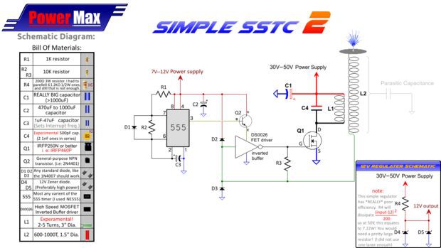
Which Power Max made a tutorial for on instructables: Easy SSTC, Slayer Exciter on Steroids! : 5 Steps (with Pictures) - Instructables
Many commenters had success with this design and reported that it was one of the best ways to produce music via a Tesla Coil.
Rather than using a DS0026 driver, I implemented a UCC37322 driver, which has an enable pin. With this IC, I could avoid the 555 and BJT, and instead just hook up a long wire pair (~10ft) to the enable pin of the IC to an Arduino Nano I programmed to produce a 64kHz PWM signal modulated by my laptop's audio output. Here's an example of this setup: (video linked under files)
Experimenting with a buck converter
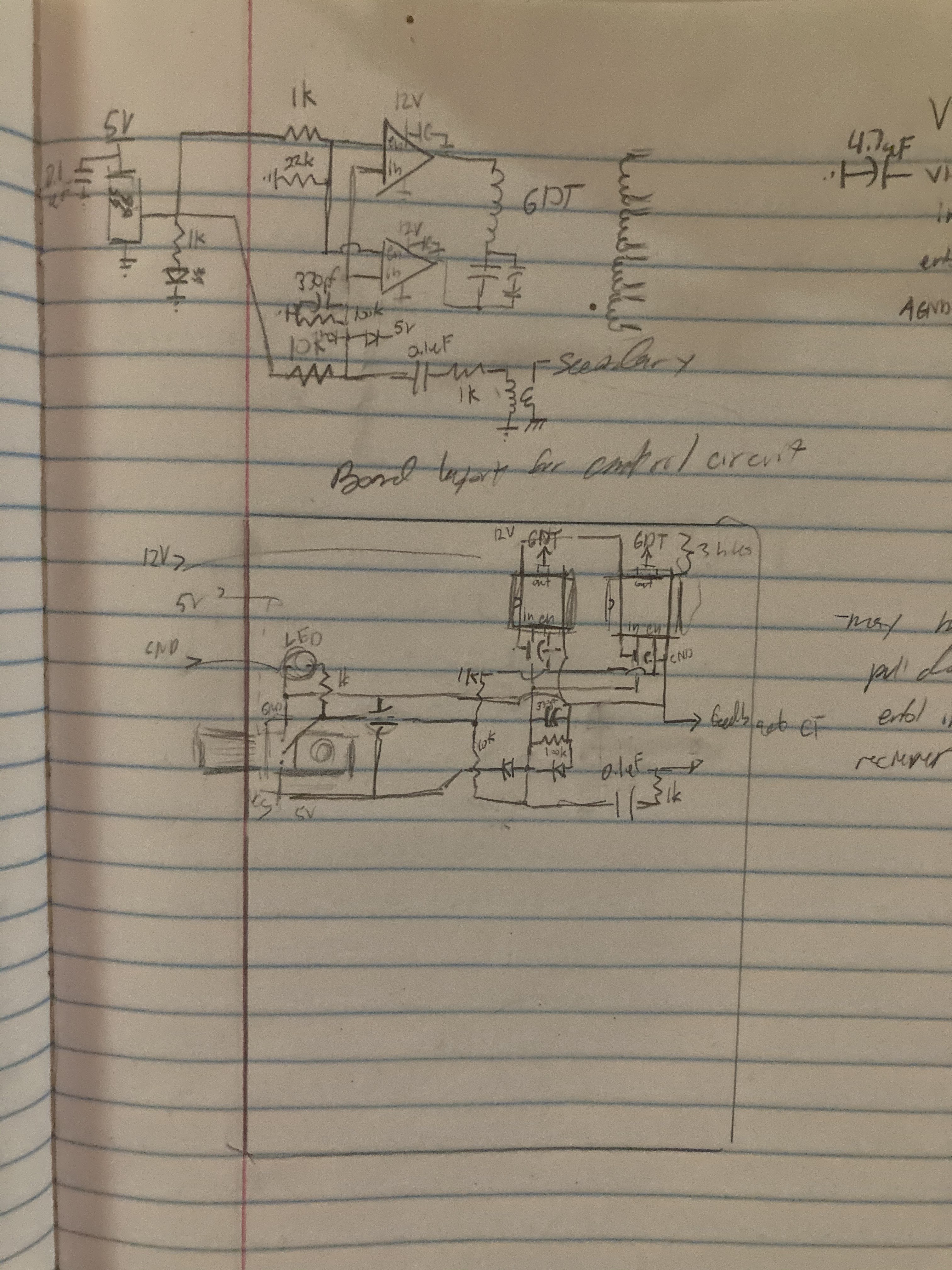
After verifying the functionality of a musical Tesla Coil, my goal became to improve the audio quality. My initial plan was to use a buck converter as mentioned previously. Before implementing the buck converter, I first wanted to develop a control circuit which could create the appropriate PWM signal. Here is the design I made:
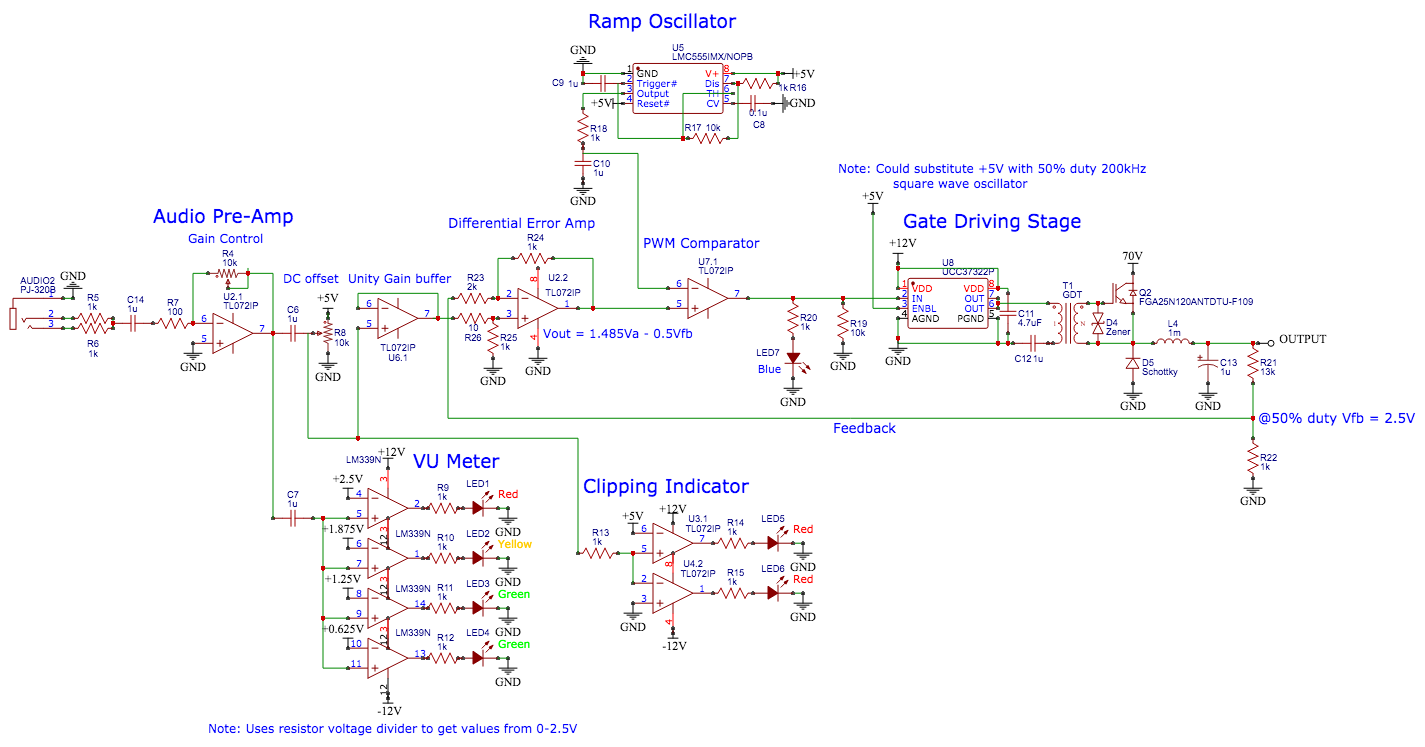
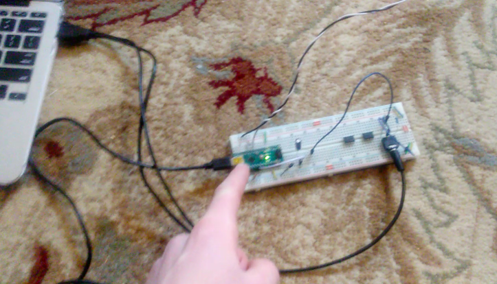
It consisted of an audio pre-amp, clipping indicator, DC offset control, and VU meter. After prototyping on a breadboard for several weeks I finally got the circuit to work.
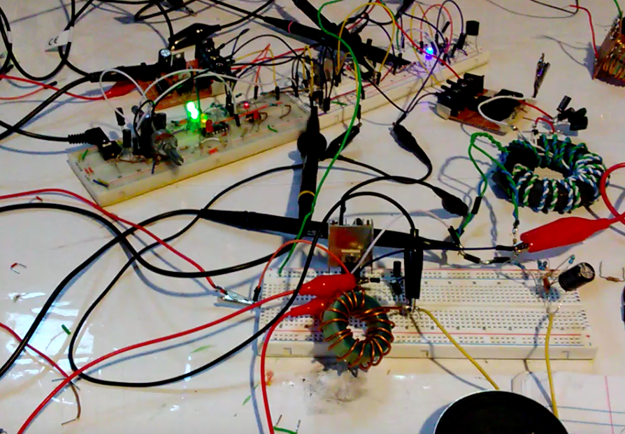
(I know wires look like a mess!)
I added a basic buck converter to the output of the controller with a generic MOSTFET I had, a choke, and a few capacitors, which I tuned to resonate at ~20kHz, thus functioning as a low-pass audio filter. The speaker I hooked up at the bottom of the image was able to play "decent quality" music from my laptop.
Here's a few images of the signal on a scope:
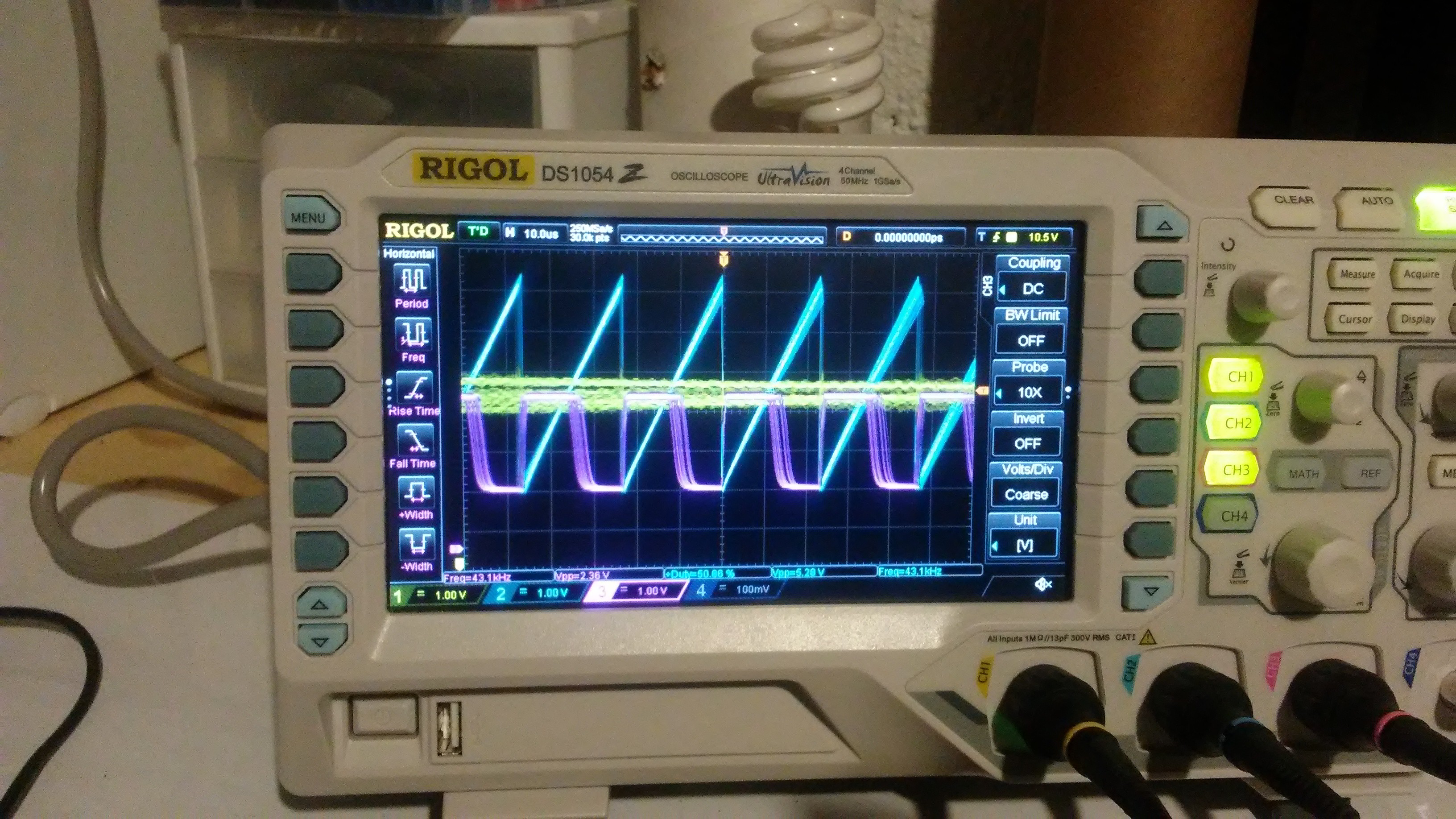
The yellow signal is the audio input, blue is the sawtooth wave, and purple is the PWM signal produced from a TL072 op-amp functioning as a comparator.
Here's an image comparing the input signal and the output from the buck converter:
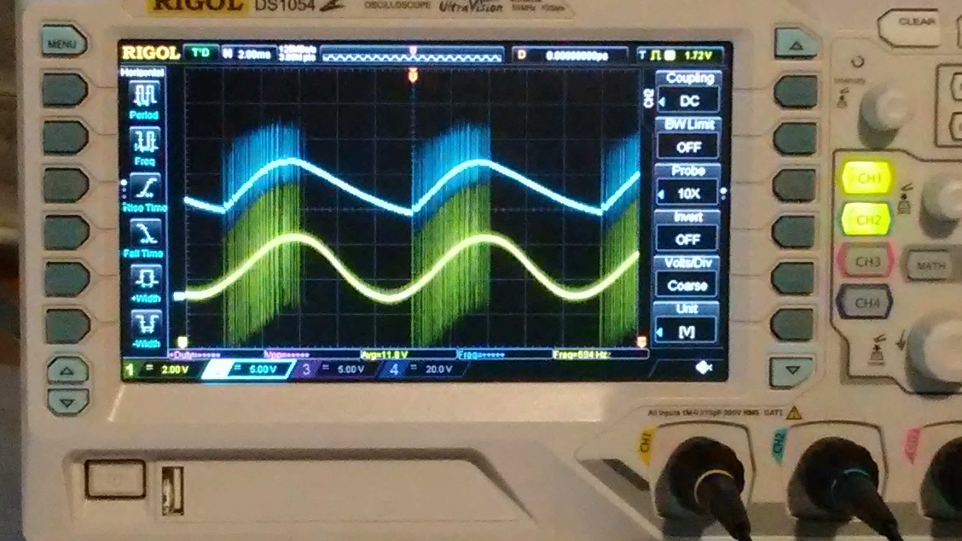
Incredibly similar. (noise before each peak is problematic though)
Going off of this design, I decided to make a buck converter using a 600V 10A IGBT. This buck converter was intended to handle the 60V DC voltage from the crude power supply I made from the transformer I had and thus power the bridge of any SSTC.
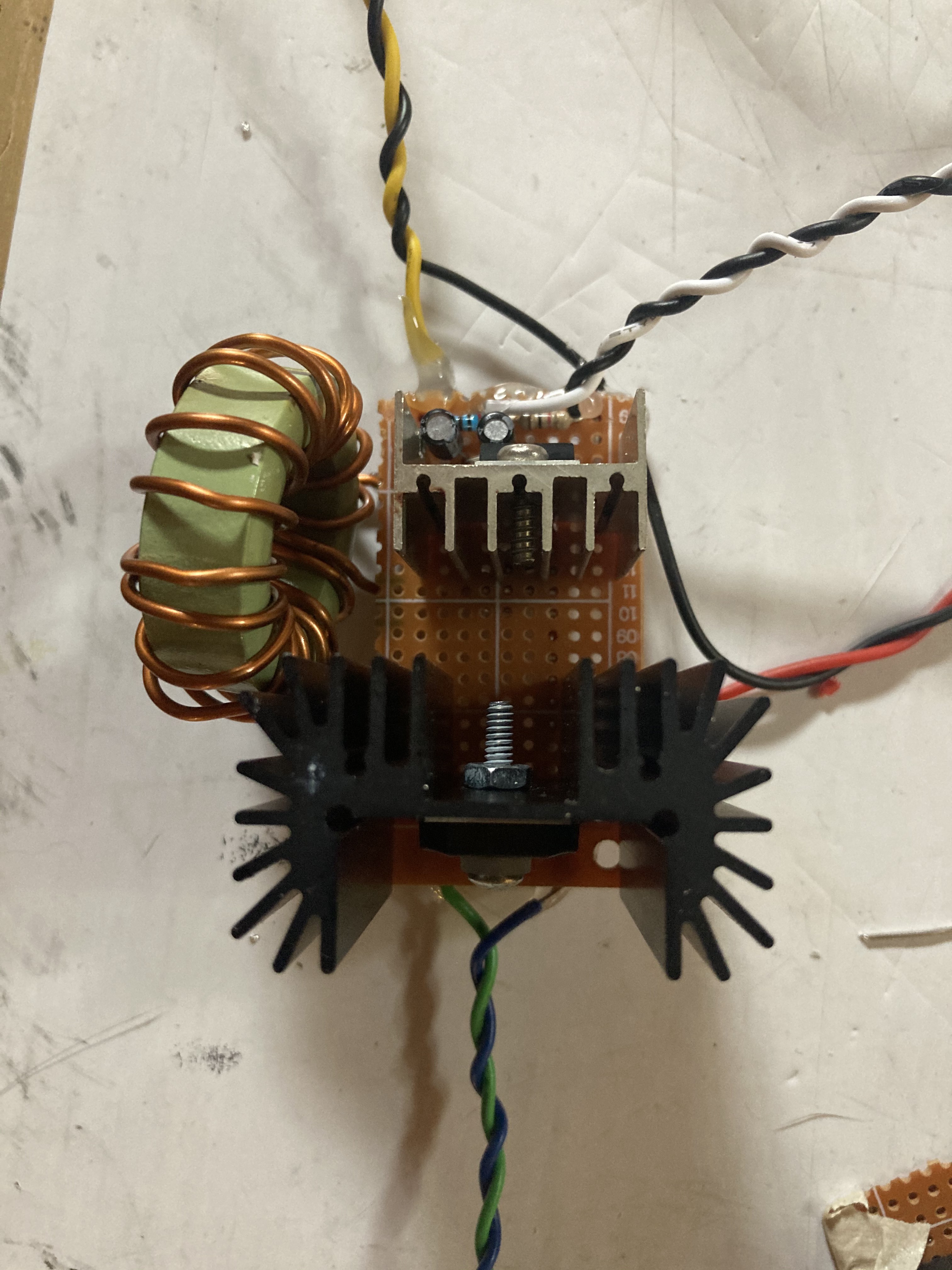
In the image above: green-blue wires are for GDT driving the IGBT, red-black for 60V input power, black-yellow for the output, and black-white for the feedback signal.
While experimenting, I decided that my previously made breadboard circuit was too messy, and after scrapping the idea of having feedback for the buck converter I opted for yet another simplistic Arduino Nano controller for the time being. However, after hooking everything up to my SSTC, powering it on, and finally starting the music, I ended up blowing a capacitor on the buck converter and destroying the IGBT! I reasoned that inductive kickback combined with the polarized aspects of a electrolytic capacitor where the fault.
I later replaced the capacitors with a single film cap and rewound the choke so that it resonated around 20kHz, but overall the buck converter seemed to fail at adequately controlling the SSTC to produce music--only making a soft buzzing noise. I then decided to scrap the buck converter idea and move forward with my a new design.
Current Design
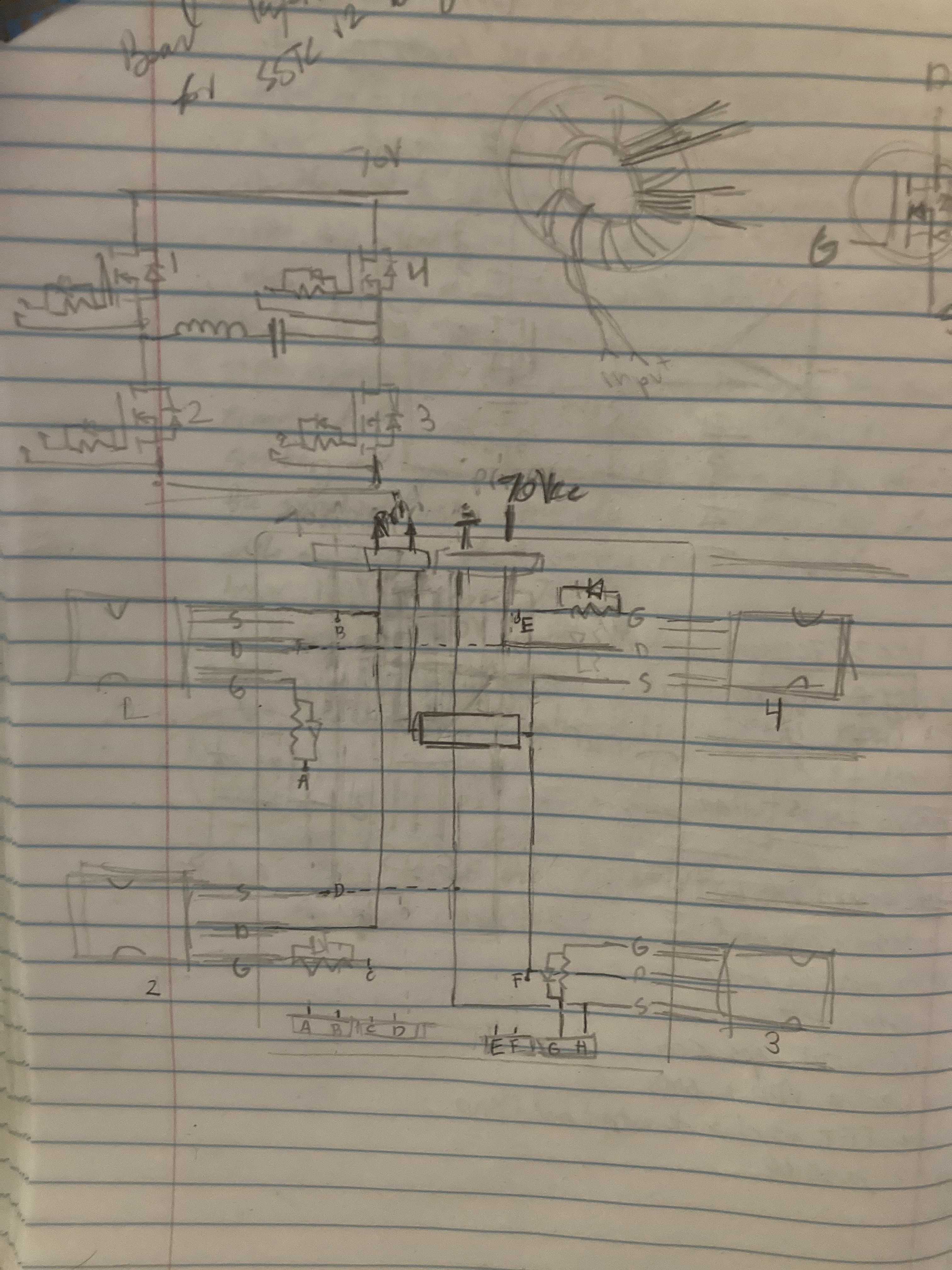
My plan currently is to develop a full-bridge SSTC while keeping the circuit as simple as possible to avoid noise and overall issues with maintaining oscillation (the issue with my previous SSTC). I'm hoping I can use an interrupter as before but this time add a feature where the interrupter can "jumpstart" oscillations through the connection of a 10k resistor to the feedback circuit--this is what OneTesla's DR-SSTC circuit implements.
Here are the sketches for the circuit I made in a notebook: