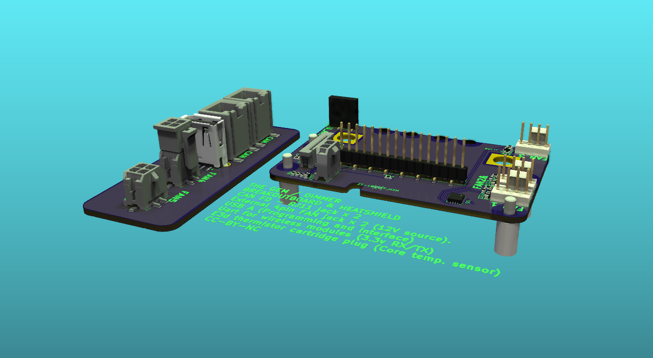
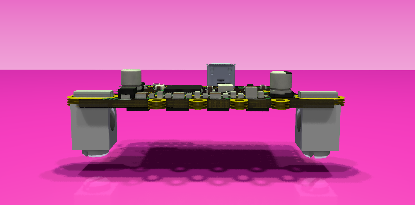
I have omitted the second CAN (RJ11) plug, since the RJ11 is bulky as it is and to save cable length. There is no need to run the CAN cable to a lamp twice if a splitter is more sensible. The Molex MicroFit 3.0 connector, for the external PWM fan, is not that tall, but it is reachable. Sometimes les is more.
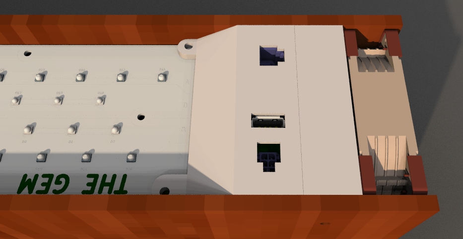
By potting the connectors, when attached to the solder point cover, we can achieve a fully air and water tight "Opening". Since we already have to make a part for the solder point cover, we might as well use that as a opportunity for Human Machine Interface HMI through USB and CAN FD. Naturally the wireless module makes it straight forward to open a handheld iOs or Android interface. There are two PWM fan ports broken out through Molex Microfit 3.0 2x2 connectors. Some may prefer a fully wired system.
In order to connect the lamp to a wired connection, a breakout is necessary. The USB power will cutoff if there is power on the 12v rail, to protect the computer motherboard.
The RJ11 CAN FD jack are compatible with DUET3.
The external FAN4 and FAN5 Micro Fit 3.0 connectors has 12v directly from PSU. The PWM signals are independently adjustable. A typical 120mm fan uses 0.5 amp at full power. The power connection for the external breakout is 9amp max.
The 4 pin header on the main shield is for wireless module UART (RX/TX) connection.
To obtain the best possible control of the LED´s, we need to measure the temperature as close as possible to the LED heat pad. This will be done using a classic E3D thermistor in a cartridge (https://e3d-online.com/products/thermistor-cartridge). The sensor is 15mm long with a 50mm cable w. a good secure connector.
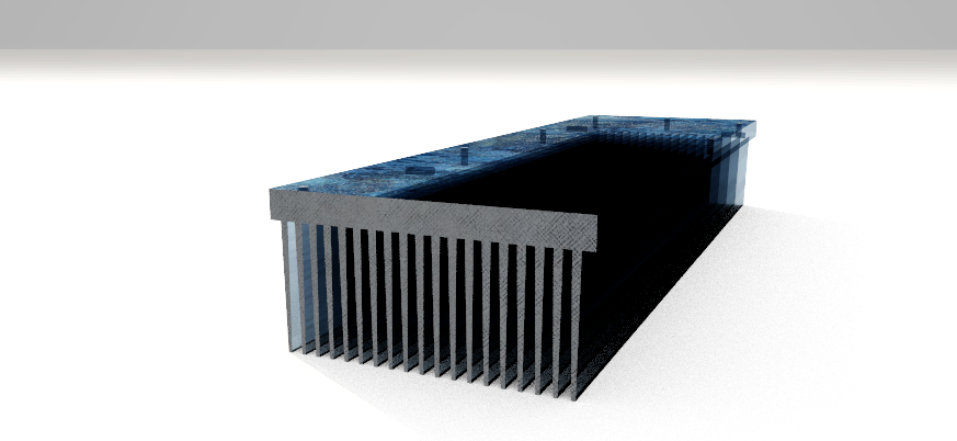
Heating or cooling the heatsink is entirely dependent on current consumption and ambient temperature.
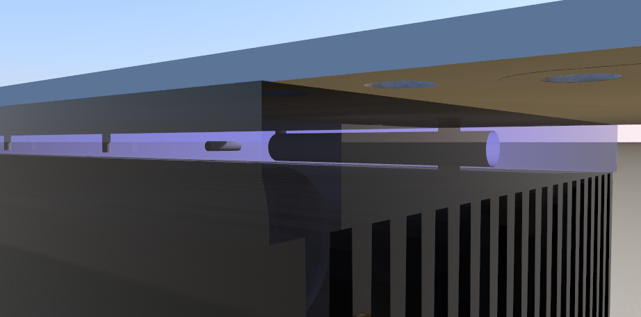
Looking at the heatsink, it is obvious, when pushing cool air across those fins, the air is gonna heat up. The above heatsink is for the small version 254mm long, 80mm wide, 40mm high.
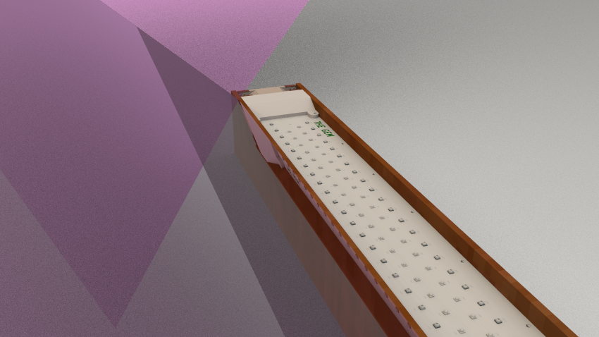
The LED phases must be soldered to the LED side, since the MCPCB is single sided. To shield of the solder points and wires, some sort of shield is is necessary.
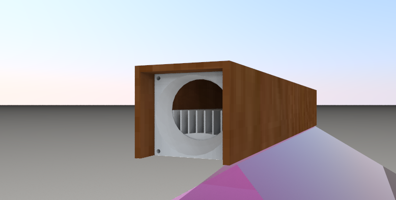
To raise the light up into the enclosure, some sort of air channel is needed. This channel will also serve as mounting bracket for the wooden enclosure. On the LED side, the channel/bracket will provide mounting holes for wire shielding.
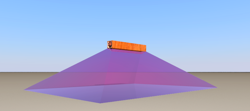
The Cree XP-G3 LED´s have a illumination angle of 125-130. Subtracting the outer 10% the grow area at 50cm height is 2m x 1m = 3m2. At 1 meter the average µmol/sek. naturally becomes lower, but will illuminate approx. 3m x 3m = 9m2. One of the advantages of LED´s for grow lights is the moderate heat radiation, which makes it possible to get close to the plants without heating up the top leaves, to much. Plants like moderate heat when utilizing the photons to produce plant matter. To achieve the best possible growth, the temperature around the leaves should be regulated. Furthermore it is a good thing to have air flowing across the leaves to evaporate moisture and thereby pull the chain of molecules going all the way down to the roots, where nutrition's are dwelling. The optimal man made system for plant growth will therefore take all these variables into account. The exces heat from the lamps, can be used to provide a optimal temperature inside the growth environment. The heat not used to regulate the growth environment can in turn be used to heat up a living space, it could be stored in eg. water or simply discarded. The trick here is to find the right balance.
 Juan-Antonio Søren E.P.