 The Curious Lorenz
Introduction
My plan is to build a frequency generator and counter by using modules I have bought years ago and which have been lying in my junk box for just too long.
I have a SI5351 module to generate square waves and a PLJ-8-LED frequency counter module.
The frequency counter module is pretty nice as it has a complete input stage and good capabilities - most probably more than I really need e.g. not in HF business myself.
The SI5351 is also quite nice and allows me to get square waves for several usages (including other kind of waveform generations - not yet designed).
Design
The frequency counter and SI5351 shall be connected to a "central unit".
The "central unit" is a AVR micro of some kind (atmega328p), a display (HD44780 or similar) and a encoder as a minimum setup.
Problem
The frequency counter module appears to offer a serial line but it actually does nothing - no activity at all.
So, there is no way to get the frequency reading from the module rather than ... sniffing the communication between the module's MCU (PIC16F648A) and the display controller (TM1369).
Analysis
All the datasheets for TM1369 I could find are written in the Chinese language. I can talk several protocols, several computer languages and (almost) 3 human languages but Chinese ... is not a thing for me :-)
There are several more popular variants of that chip and the actual protocol is the same. The differences are in how the bytes are transmitted and the memory layout - but not the commands.
TM1369 works in SPI mode thus the atmega328p will be the slave unit sniffing these bytes.
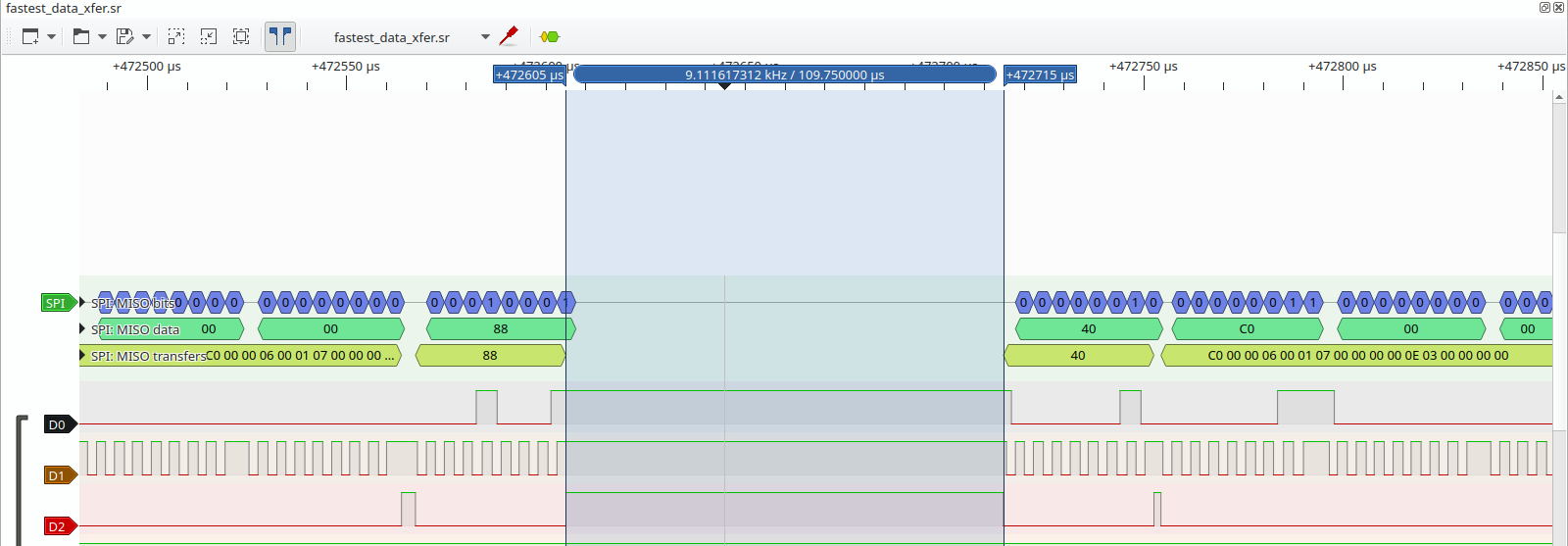
The module transmits "Address Command; Data Command and Display Command" in 19-bytes bursts. The pause between these bursts depend on the state of the MCU: the following diagram shows the quickest pause I could measure and this is the baseline measurement for the software design.
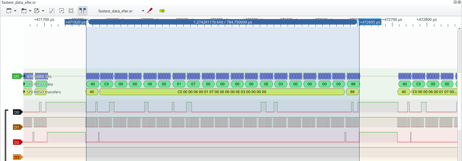
Here instead, the full packet:
Goals
- Read the TM1369 at 8MHz no crystal (so to support a wide range of MCUs).
- Almost no logic to keep the "state" of the transfer.
- Read can be crafted for the specific module i.e. does not support all TM1369 interfaces.
Design to reach goals
- Keep the SPI interrupt as short as possible: just store the received byte in a buffer and leave.
- Utilize a "buffer index" variable only. It is reset exactly when 19 bytes have been read or when the "inactivity" timer expires.
- Side effect of the 19 bytes boundary, the timing boundary and usage of a fixed buffer i.e. byte positions of the protocol.
Design using a atmega328p
8MHz clock
SPI Slave unit using interrupt to store the received bytes into a buffer.
Timer unit as a "payload burst end" signal which resets the "buffer index".
The timer is setup as CTC ("Clear Timer Compare Match"). An interrupt routine is executed every 80us if not reset by the SPI reception interrupt routine. The timer expiration value has been selected based on the 110us minimum pause between 19-bytes payload burst and the about 50us maximum time to receive a SPI 8-bit word.
The pinout is the following (please note that it also documents part of the envisaged design of the overall
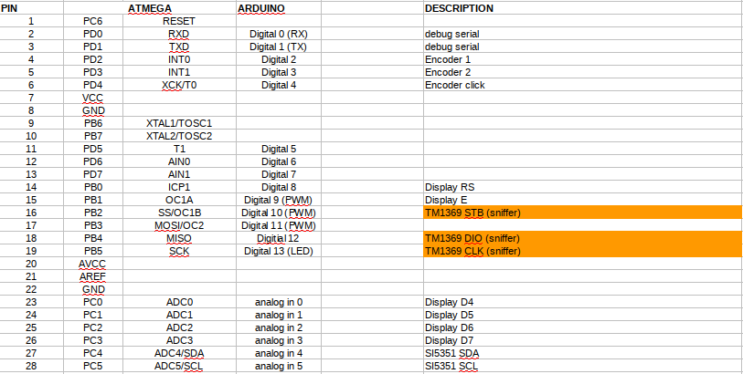
signal gen/counter project).
Demo software
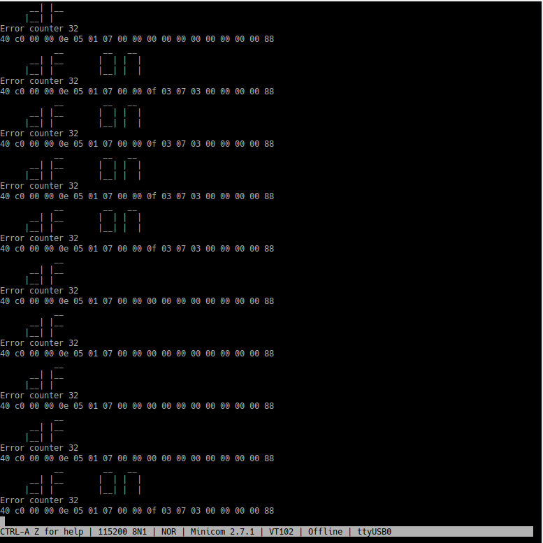
The demo application reads the TM1369 communication and displays its content to the serial port as simulated 7-segments characters. Currently, no VT-102 "terminal commands" are used, hence the serial port works sequentially.
The result is quite interesting and it works pretty well. For example, here the display of the "dF" setting can be seen from the serial log. Indeed, the "ON" string is blinking with a period of around 300ms or so.
TODO: github repo with testing code (decoding and printing as 7-segments on the serial port)
Final considerations
Of course, all of that is not black magic and can be vastly improved. For example, a larger buffer can be employed (and adapted on a per-project basis) and the main loop can examine these bytes to actually work like a TM136x unit, filling the...
Read more »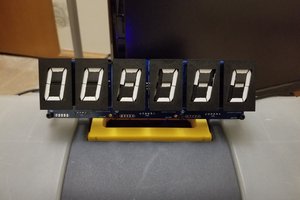
 sjm4306
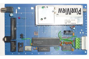
 Keith
Keith
 Lauri Pirttiaho
 benw
benw