 Victor Chan
Prologue
Original version of this clock started around March 2017. This happened by somewhat of a coincidence, as I noticed that the bedroom clock seemed to slow down quite noticeably only after a few weeks. That and the annoying task of replacing batteries every 6 months or so definitely didn't help. This was where a decision was made to build my own clock.
Initial Design
Firstly, the main goals of the design were determined. They were very basic and simple:
- Accurate
- Maintenance free
- Versatile
Design was carried out on a breadboard with simple jumpers and LEDs with the 3 goals in mind. GPS was used for accuracy. Even though higher accuracy can be achieved with the timing coming off the PPS signal, this was not possible without embedding the GPS module directly onto the clock. Thus the GPS module (puck) for automotive navigation systems were the obvious choice. It is easy to use and outputs the NMEA strings which can be easily parsed by the MCU. Only the GPRMC and GPGGA strings are recognized as they contain the data fields we needed. Accuracy of around 0.2s or less can be easily achieved. This is not an issue as the main goal is for normal daily time keeping, and not for time recording of critical machine / equipment events (which may often need to be 10 ms or better).
Main maintenance item would be the battery. Getting rid of battery is a big thing for me. Time accuracy is not so much of an issue as GPS data will provide the corrected time once lock is obtained. However, to be useful, the clock should be able to run even when GPS lock is not available. Simpler implementations that solely parse the GPS data for time display will be unable to display the time when there is no GPS data. This is where the RTC helps to keep the clock running (free running mode). Updating the firmware was also an important consideration. Therefore, the 5 pins for ICSP are provided so that new firmware can be easily flashed.
There were a few important items under the versatile category:
i. Large display - the 2.3 inch digit size chosen is the ideal size for this use case.
ii. Readability - LED brightness must adapt to the ambient lighting accordingly. Otherwise, it may be too bright at night and dim during the daytime.
iii. Power needs - single power source for the electronics and the 2.3 inch LED display. The clock MCU, RTC and RF module all run at different voltages than the LED display.
iv. Seamless operation - the nearest window from the wall where the original clock hung was not conveniently near enough to pull the GPS antenna module, without messy long wires. This meant that the data must be wirelessly sent to the clock. NRF24L01+ is the perfect candidate for size, ease of use and cost.
v. Constant time keeping - living in a high rise building with other similarly tall buildings nearby pose some challenge to the GPS signal stability. Therefore, GPS signal outages are expected. Depending solely on the NMEA string to provide time also means that the RF module has to be powered on at all times. The solution? DS3231 RTC.
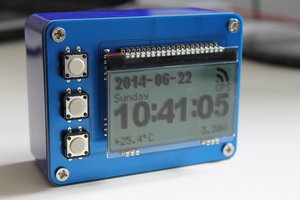
vi. GPS info - since it runs on GPS, it is useful to know how strong the GPS signal is being picked up. Looking at the FIX LED will not provide much info besides when it does or doesn't have a FIX. Therefore, the satellite count / quantity will be more beneficial. This is implemented on this clock.
Parts Selection
Main technical challenges were parts selection, testing and debugging. So, let's see what has to be right in the design and my choices for the parts selection:
i. RF module : Decent range in the ISM band, which immediately restricts it to 2.4 Ghz. Widely used and fairly easy to work with. Doing some research, I kept coming back to the Nordic Semiconductor IC based module, NRF24L01+. These have been on the market for a number of years and a decent amount of documentation were available.
ii. RTC IC : Accurate and since GPS can provide date, preferably it includes a built in calendar....
Read more »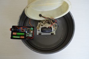
 hkdcsf
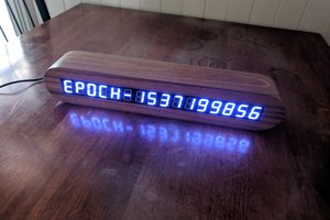
 clewsy
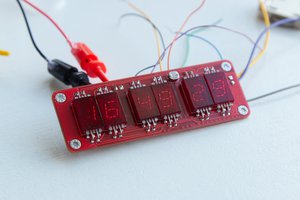
 Stephen Holdaway