 John Duffy
GOT IT!
Figured out how to make ohms work well. Was looking for a way to get the ranges to overlap better, which would be helped by dropping some voltage (even at very low currents, in the uA range) from the source while keeping the output voltage somewhere around 1.5V and decent drop across the high-side shunt.
I asked on the stack (and previous log) for a part with a relatively consistent voltage drop from a couple mA down to a few uA, if anyone's looking for a good solution to that problem, a 2-terminal voltage reference, Paul Stoffregen suggested a REF1112, does exactly that. For some reason I didn't think about a source-follower mosfet though (that doesn't work for the question as asked, but does work for this system as a whole). Finally got around to actually simulating something since I'm away from home and can't test it in person, so I've got a piece of the schematic:
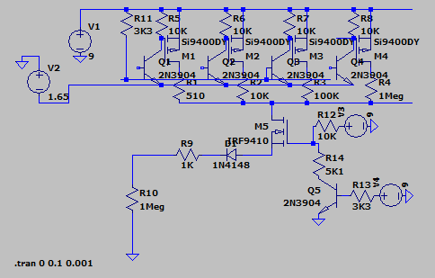
It's not super clean, but all the stuff up top is effectively just some pfets switching the 510, 10K, 100K or 1Meg resistors to the 9V rail. R10 is the resistor being tested, R9 and the diode are input protection, M5 is the source follower (the new part), and Q5/R12-14 are just to enable and set the voltage for that (disabling Q5 lets the output voltage swing up to the full 9V). For high value ohms, this would be enabled to keep the DUT voltage right at about 1.65V, below a few K, this can be disabled as R9 provides enough voltage drop at the higher measurement current. I know this isn't a great explanation, planning to do an actual run down of how all this works once it's working but don't have a ton of time right now.
That said basically the way ohms works is, the voltage measurement path (not shown, impedance ~= 10Meg, which will have to be factored in during measurement but can be ignored for this) is connected to the high side of R10, we then put some amount of current through R9, by knowing that current and the voltage across R10, we have ohms. Since we're effectively kelvin sensing at that node, R9 and D1 (input protection) won't affect the measurement. There will be other stuff as well that makes it more impractical to control accurately. One of R1 through R4 is switched to the 9V rail, we then measure the voltage across it (plus a pfet, but Rdson is in milliohms so can be ignored for now), so we know the current going through it, and thus R9 since there's nowhere else for current to go. This voltage is tapped off at the two wires going out the right at the top of the image, goes to an opamp and pfet which converts the voltage to a current from the 9V rail towards ground:
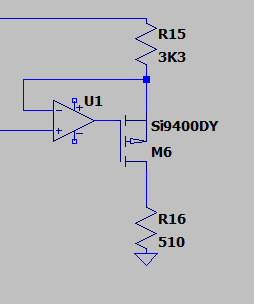
The ratio of R15 to R16 sets the attenuation (since the shunt might have 6+ volts across it, and we have to reduce that to ~1.5V). We measure across R16, since the current coming down is proportional to the measured voltage, this converts it back to a voltage, but now shifted to be relative to ground (remember shunt voltage is coming from 9V, which is coming from a switcher operating at very low load, so may be noisy or somewhat unstable relative to ground.
Switching between R1, 2, 3, and 4 (510 ohms to 1Meg) we get different ratios of volts per amp (so with a 1Meg shunt, if we're putting in 1uA, we'll see 1V across it, and thus R15, and thus 0.145V across R16). The voltage across R16 is what goes into the ADC as measured current.
Discussions
Become a Hackaday.io Member
Create an account to leave a comment. Already have an account? Log In.