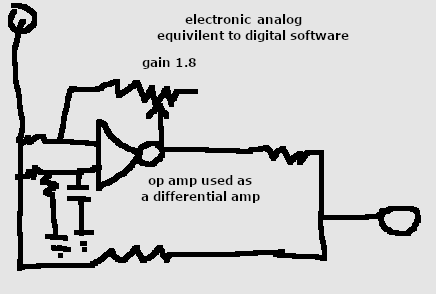
i need to explain. this is not a filter in the normal sense. it does not average out the data. the high pass filter described below is just used as a feedback loop into the raw data. the raw data still needs further filtering, but here we are just trying to reduce variations from noise. the raw output will always have wide swings, until properly filtered if sampling at high speeds for example 30-50 times a second. in software the filtering is like this circuit below. the gain is adjustable to cancel out the correct amount. the raw dat goes in, and comes out with inverted difference of a low pass filter and a comparator of raw data from differential amplifier that gains the signal to invert and compensate output. it is more like noise cancelation, or noise reduction, as it still leaves most of the raw data value there, just removes the spikes that are above average.
i'm trying to get accurate high speed sample measurements, i know the sensor can do better accuracy when measurements are at 1 time a second. but when doing 30 times a second sampling noise issues are an effect 1 of the following:
1) out of spec voltage low measurements on the chip (even when voltage regulation is stable and external capacitors)
2) laser power variation most likely from voltage spikes and internal compensation
3) voltage spike swings between measurements.
it is difficult to filter out the voltage as it's phase slightly shifts, and the laser power variation is similar. so i'm taking a different approach, isolate the higher frequencies to cancel them out.
here is what i came up with.
(f(2)*0.9+ f(1)*0.1 -f(2) )*gain(1.8)=Δ higher frequency pass filter that is inverted and applied to the raw data
f(2)- Δ=compensated distance output
this graph shows old method. red is 2.2 less than blue. (max-min)
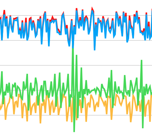
green: voltage Δ x 100, yellow: cds sensor for laser power output
blue: output variation unfiltered MM distance 30 times a second variation (max-min)=34
red: trying to compensate voltage and laser output. deviation (max-min)=31.8
i'm having issues looking at voltage and laser output and getting more than 2.2 reduction in noise (all of this is with removing out of spec voltage measurements)
now when i drop the looking at the voltage measurement except for making sure it is in spec, and drop the laser measurement, and just look at removing the high frequency components of the data here is what i get.
keep in mind this is not averaging it is inverting the high frequency.
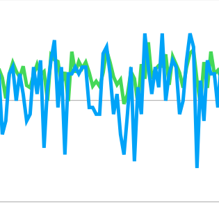

with using a high pass filter to create inverted feedback to the raw data the delta of it we get a variation (max-min) of 13.8 so this seams to be the way to go. keep in mind these are raw measurements and when filtered properly should average out over time. i can easily implement this method of noise reduction before filtering data. gain needs to be automatically determined, as well as dc offset so still some more work to do. in this case gain was set to 1.8 and offset was 20 so graphs data would overlap.
data used is in files reduceNoise1.xlsx, and reduceNoise2.xlsx
so next is to move out of excel and into real use.....
Discussions
Become a Hackaday.io Member
Create an account to leave a comment. Already have an account? Log In.