 kutluhan_aktar
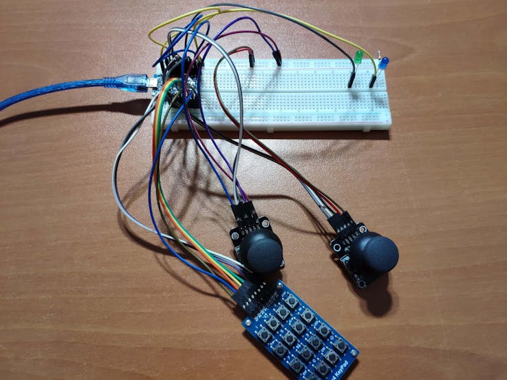
First of all, to be able to send keyboard and mouse commands via USB, I used an Arduino Pro Micro centered around an ATmega32U4 - an 8-bit AVR very similar to the ATmega328. The ATmega32U4 comes equipped with a full-speed USB transceiver, which can emulate any USB device.
Then, I utilized the 4x4 matrix keypad design to send keyboard keys, supporting up to 32 keys with two dynamic keypad options.
Finally, I used two joysticks as a fully-functional mouse, also controlling the dynamic keypad options and modifier keys.
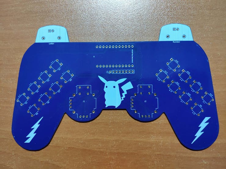
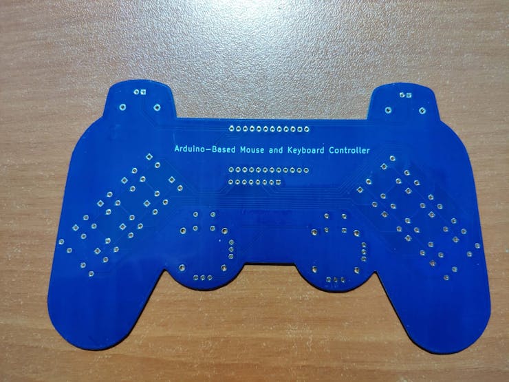
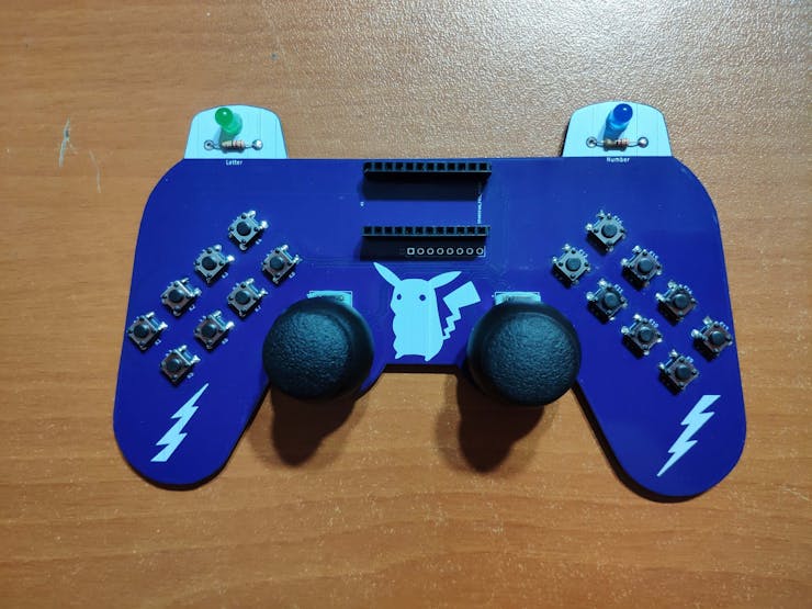
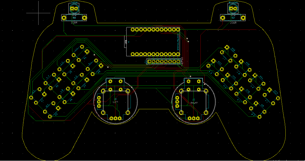
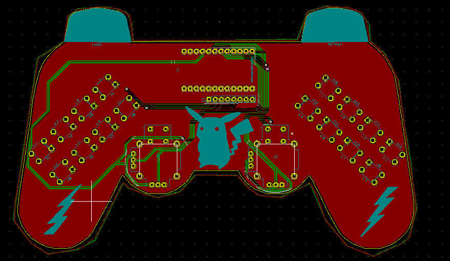
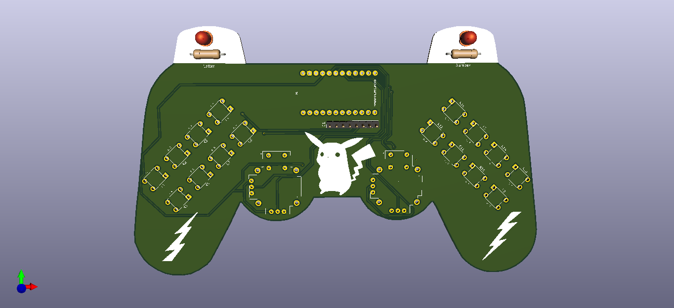
After completing my design on a breadboard and testing the code, I designed a controller-shaped PCB (Arduino-Based Mouse and Keyboard Controller) with an integrated 4x4 matrix keypad and two embedded joysticks, displaying Pikachu as its center logo :)
Huge thanks to PCBWay for sponsoring this project.
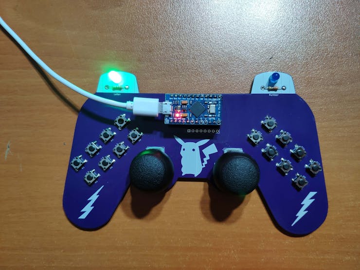
Step 1: Designing and Soldering the Mouse and Keyboard Controller PCB
Before prototyping my PCB design, I tested all connections and wiring with the Arduino Pro Micro on the breadboard.
Then, I designed the Mouse and Keyboard Controller PCB by using KiCad. I attached the Gerber file of the PCB below, so if you want, you can order this PCB from PCBWay to create a stylish and fully-functional USB Keyboard/Mouse displaying Pikachu as its center logo :)
Click here to inspect and order this PCB directly on PCBWay.
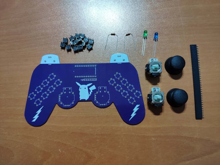
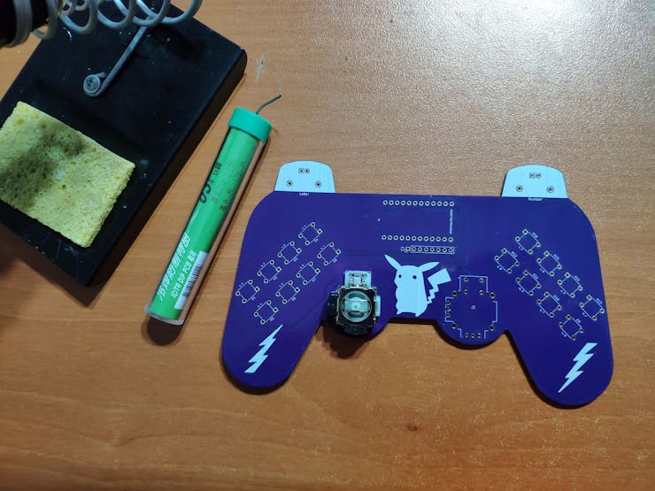
First of all, by using a soldering iron, I attached headers (female), COM-09032 analog joysticks, 5mm green LED, 5mm blue LED, 6x6 pushbuttons, and 220Ω resistors.
Component list on the PCB:
A1 (Headers for Arduino Pro Micro)
J1, J2 (COM-09032 Analog Joystick)
K1, K2, K3, K4, K5, K6, K7, K8, K9, K10, K11, K12, K13, K14, K15, K16 (6x6 Pushbutton)
D1 (5mm Green LED)
D2 (5mm Blue LED)
R1, R2 (220Ω Resistor)
C1 (Headers for External Keypad)
Step 2: Setting up the Pro Micro in the Arduino IDE
Before coding, we need to add and verify the Pro Micro board settings on the Arduino IDE. With the latest release of Arduino IDE, adding third party boards to the IDE is easily achieved through the Boards Manager.
⭐ Open up the Arduino IDE, then go to the Preferences (File > Preferences). Then, towards the bottom of the window, paste this URL into the "Additional Board Manager URLs" text box:
You can add multiple URLs by clicking the window icon and pasting one URL per line.
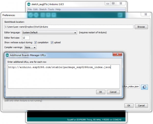
⭐ Click OK. Then, open the Boards Manager by clicking Tools > the Board selection tab > Boards Manager.
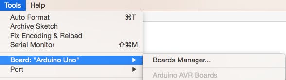
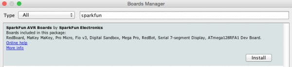
⭐ Search for "sparkfun" in the Boards Manager. When the SparkFun AVR Boards package appears, click install, wait a few moments until the IDE confirms all the installed .brd files.
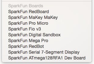
⭐ Now, select the Sparkfun Pro Micro board under the Sparkfun Boards to upload code to the Pro Micro.
Step 3: Programming the Arduino Pro Micro
⭐ Include the required libraries.
Keypad | Library
Keyboard | Library
Mouse | Library
⭐ Define the symbols on the buttons of the dynamic keypad options - letter and number.
⭐ Initialize the dynamic keypads.
char letterKeys[ROWS][COLS] = { {'e','a','r','i'}, {'o','t','n','s'}, {'p','m','h','w'}, {'l','c','u','d'}};char numberKeys[ROWS][COLS] = { {'1','2','3','+'}, {'4','5','6','-'}, {'#','0','*','%'}, {'7','8','9','/'}};byte rowPins[ROWS] = {6, 7, 8, 9}; // Connect to the row pinouts of the keypad.byte colPins[COLS] = {2, 3, 4, 5}; // Connect to the column pinouts of the keypad.// Initialize an instance of class NewKeypad for each keypad setting - letter and number.Keypad letterKeypad = Keypad( makeKeymap(letterKeys), rowPins, colPins, ROWS, COLS);Keypad numberKeypad = Keypad( makeKeymap(numberKeys), rowPins, colPins, ROWS, COLS);
⭐ In the read_joysticks() function, collect the data generated by joysticks - J1 and J2.
void read_joysticks(){ joystick_left_x = analogRead(VRX_L); joystick_left_y...
Read more »

 kefcom
 Jim Heaney
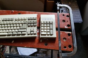
 Charles
 DefProc Engineering
Please feel free to leave a comment here if you have any questions or concerns regarding this project 😃