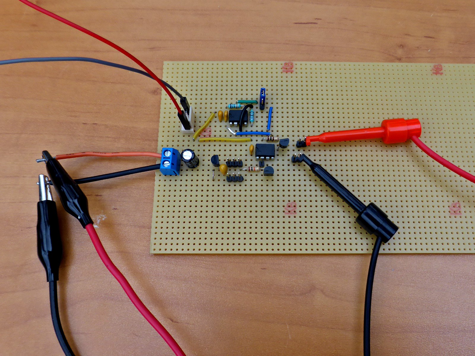
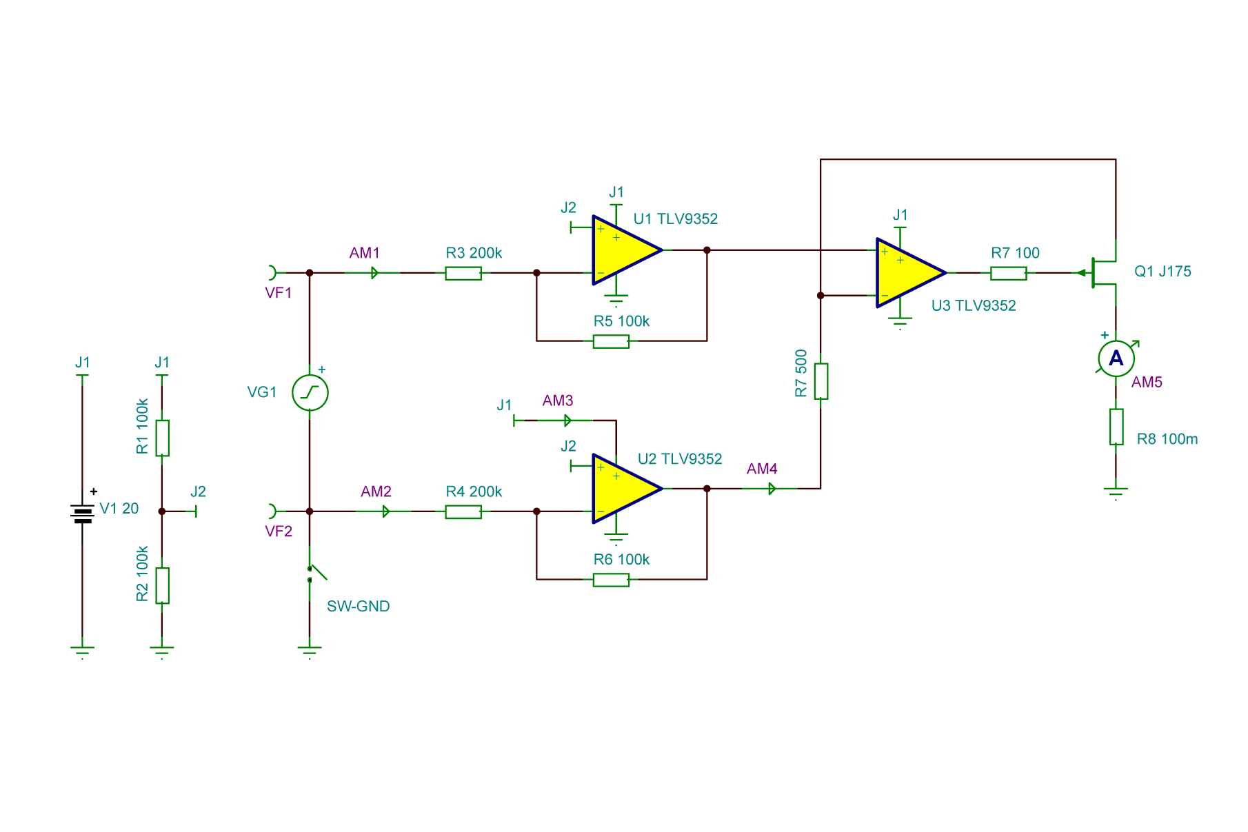
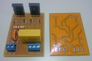
• Prototype board test

    Krists02/26/2021 at 17:32 0 comments

    For testing I made prototype using somewhat lower spec TS272C opamps. Is has some limitations but works quite promising. There is additional 5V and 2.5 V converters on prototype board that is not on schematic. As I trust in my DM3058E I hand picked and fine tuned exact resistor values. Initial conversion accuracy is really good. Somewhat problem is that circuit does not work well if separate mains referenced devices are connected to input and output like function generator and multimeter. Although outputs and inputs of these are supposed to be floating in reality they are not. Only thing floating (except for batteries) in my lab is power supply... as it is linear one with true isolating transformer inside. Measuring batteries, however works quite well. Besides 1:1000 range there is 1:200 range settable by jumper but it seems to be slightly off.

  • Proposed schematic and initial specs

    Krists02/26/2021 at 17:28 0 comments

    I suppose to build the circuit around Texas Instruments TLV9352 opamps and P-channel JFET transistor. TLV9352 opamps are listed surprisingly cheap with wide operation voltage up to 40V and good current sourcing capability.

    Specs of the device would be:

    Input (measured) voltage up to 40 V that should be matched with power supply for the device. Like, to convert 20V input (referenced to negative rail or differential / floating) 20 V supply should be used.

    1:1000 voltage to current ratio. 1V input will source 1 mA to output, 10V will source 10 mA and so on. Probably additional 1:100 range can be used for input voltages up to 4 V. For that some jumpers (not nice) or relays (nice clicking) can be used.

    Conversion precision:  ±0.5 %. Bandwidth: up to 1 Mhz. Can convert only positive voltages with + input more positive that -.