Stefan Wagner
Features of the SAMD21E
The SAM D21E is a series of low-power microcontrollers using the 32-bit ARM Cortex-M0+ processor with up to 256 KB Flash and 32 KB of SRAM. The SAM D21E devices operate at a maximum frequency of 48 MHz and reach 2.46 CoreMark/MHz. They are ideal for a wide range of home automation, consumer, metering, and industrial applications. All devices include intelligent and flexible peripherals, Event System for inter-peripheral signaling, and support for capacitive touch button, slider, and wheel user interfaces.
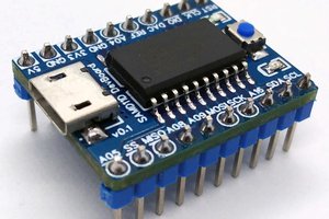
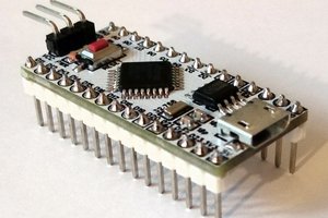
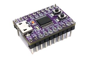
The following microcontrollers (TQFP-32 package) can be used with this development board:
| Controller | Flash | SRAM |
|---|---|---|
| ATSAMD21E15A/B | 32 KB | 4KB |
| ATSAMD21E16A/B | 64 KB | 8 KB |
| ATSAMD21E17A | 128 KB | 16 KB |
| ATSAMD21E18A | 256 KB | 32 KB |
All microcontrollers have the following features:
- ARM Cortex-M0+ CPU running at up to 48MHz
- Single-cycle hardware multiplier
- Idle and standby sleep modes, SleepWalking peripherals
- External Interrupt Controller (EIC) with 16 external interrupts and one Non-maskable Interrupt (NMI)
- 12-channel Direct Memory Access Controller (DMAC)
- 12-channel Event System
- Three 16-bit configurable Timer/Counters (TC)
- Three 24-bit Timer/Counters for Control (TCC), with extended functions
- 32-bit Real Time Counter (RTC) with clock/calendar function
- Watchdog Timer (WDT)
- One full-speed (12Mbps) Universal Serial Bus (USB) 2.0 interface with embedded device and host function
- Four Serial Communication Interfaces (SERCOM), each configurable to operate as either:
- USART with full-duplex and single-wire half-duplex configuration
- I2C Bus up to 3.4MHz
- SMBUS/PMBUS
- SPI
- LIN slave
- 12-bit, 350ksps Analog-to-Digital Converter (ADC) with up to 10 channels
- Differential and single-ended input
- 1/2x to 16x programmable gain stage
- Automatic offset and gain error compensation
- Oversampling and decimation in hardware to support 13-, 14-, 15- or 16-bit resolution
- 10-bit, 350ksps Digital-to-Analog Converter (DAC)
- Two Analog Comparators (AC) with window compare function
- Peripheral Touch Controller (PTC): 256-channel capacitive touch and proximity sensing
- Two-pin Serial Wire Debug (SWD) programming, test and debugging interface
- 26 GPIO pins
- Operating Voltage: 1.62V – 3.63V
- I/O Pin Current: max 7mA
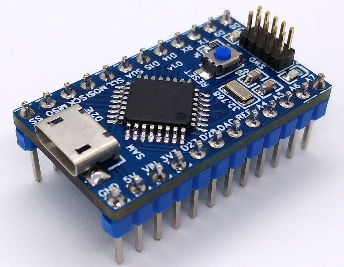
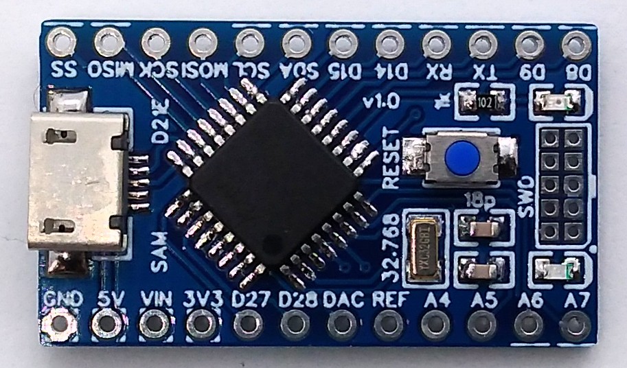
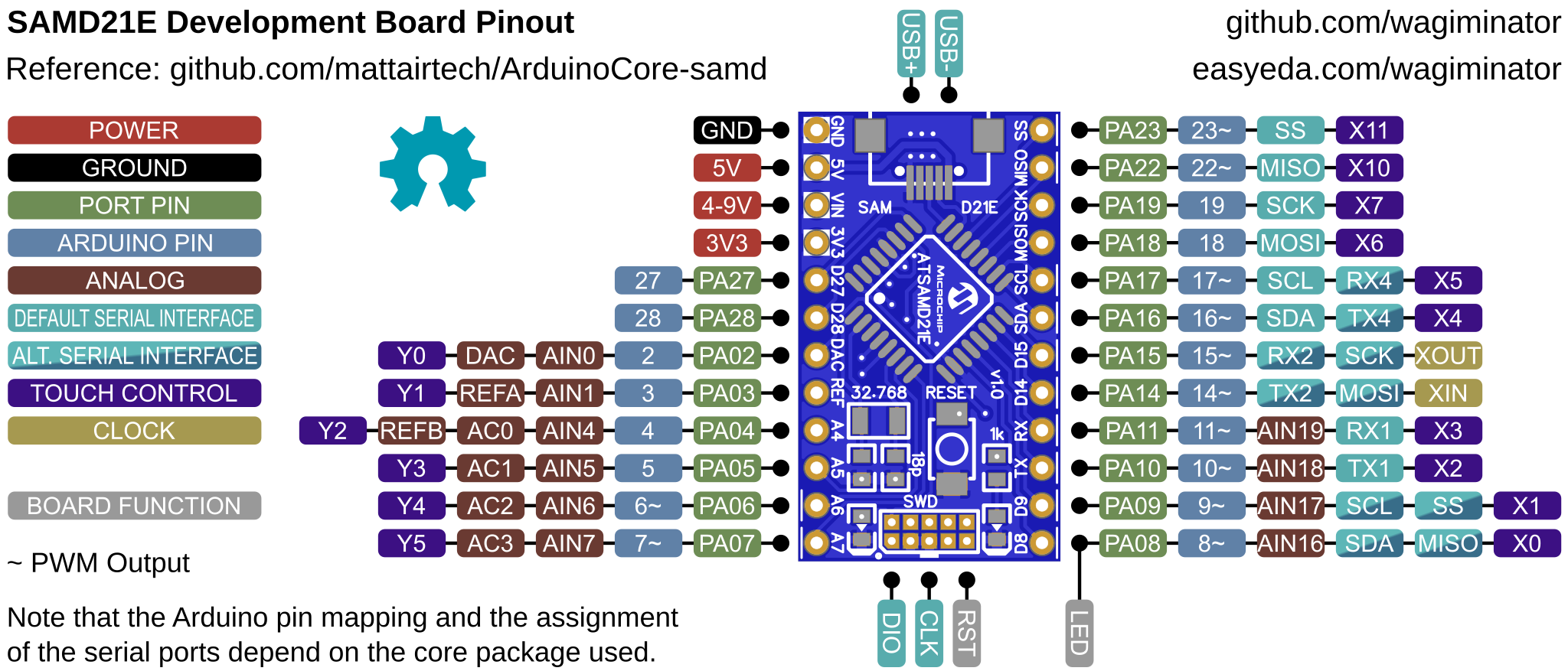
Pinout
Preparing Arduino IDE and Installing Bootloader
- Install SAMD Core
- Open the Arduino IDE
- Go to Tools -> Board -> SAMD DevBoards and select SAMD21E DevBoard
- Go to Tools -> Microcontroller and select the MCU of the board
- Go to Tools -> Bootloader and select 8kB Bootloader
- Go to Tools -> Programmer and select your programmer
- Connect your programmer to the board und to a USB port of your PC
- Power the board
- Go to Tools and select Burn bootloader
- Disconnect the programmer
If a sketch with CDC support is installed on the board, the bootloader is activated automatically when a sketch is uploaded via the Arduino IDE. Otherwise you have to enter the bootloader manually before uploading. This can be done either by pressing the RESET button twice in quick succession or by pressing and holding the RESET button while connecting the board to the USB port of your PC. The activated bootloader mode can be recognized by the fading of the built-in LED.
With the uf2 bootloader (SAMD21E18A only) the board also appears in the file manager as a USB mass storage device. A compiled sketch can therefore also be transferred to the board by drag and drop.
If you want to install a bootloader without the Arduino IDE, refer to the readme.txt inside the bootloader folder.