 Jithin Sanal
Story
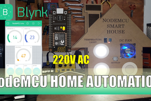
In this post, I will show you how you can set up an Alexa Home Automation using Arduino. I will be giving you complete instructions including the circuit diagram, PCB files if you want to make a PCB, and the codes. I will provide the link to everything in the description so that you can redesign the entire thing, customize it and then make your own version of it.

DIY Alexa Home Automation Video Tutorial
In this video, I will show you how you can set up an Alexa-based Smart Home using Arduino. I will be giving you complete instructions including the circuit diagram, PCB files if you want to make a PCB, and the codes.
I will provide the link to everything in the description so that you can redesign the entire thing, customize it and then make your own version of it.
Components Needed
The following are the components that are needed to build your Alexa Home Automation System using Arduino
- Arduino Nano 33 IoT (or any WiFi-enabled Board)
- SSR
- An Android Phone with Alexa App installed
- A WiFi network
To set one up, the first thing you need is to select an Arduino board. For this project, I’ll be using this Arduino Nano 33 IoT. This enables us to control the devices using Alexa in your mobile phone as well as from echo dot. The Arduino Nano 33 IoT is the best Arduino board available if you want to add network connectivity to your project. This is an IoT board, light, and compact and it’s the same size as that of nano. Yes, you can use any board with network connectivity for this project.
Why not make a PCB for your Project?
Making a PCB for your DIY project is not hard nowadays. PCB helps to get rid of all messy wires and stuff and give your project an awesome look. And its cool to make your own PCB for your project right?
Getting PCBs Done
I usually order our PCBs from PCBWay. PCBWay is a PCB manufacturer specializing in PCB prototyping, low-volume production, and neat and tidy PCB Assembly for a very low price. They have a very friendly customer support team and even perform a free PCB Design Review before payment and inform us if there is some issue with the design. Feel free to check out their website below.
Make your own PCB for your Project
Alexa Home Automation System Circuit and PCB Layout
First, take a look at the circuit diagram.
Here we are in Altium designer. Here I will be connecting LED strips that work on 12 V So, I will be connecting a 12 V DC adapter. The input power is connected to a 7805 regulator. 7805 is a 5V regulator which will convert an input voltage of 7- 32V to a steady 5V DC supply. There are indicator LEDs across various points for easy troubleshooting.

Here, there are 2 voltage inputs – One to power the Arduino and other components on the board and another which will drive the electronic devices connected to the relay, which will depend on the devices.
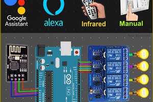
Four GPIO pins of Arduino are connected to SSR or Solid State Relays which is a type of Relay. Relays are switching circuits that can close and break circuits mechanically. That means it can control an electrical circuit by closing and breaking connections in that circuit.
A solid-state relay (SSR) is similar to a type of Relay. SSR is basically an electronic switch that switches on & off when a small external voltage is applied across its control terminals. We will be using these relays in our Arduino Smart Home.

Of course, you can use an electromechanical relay for this project. If you are using an ordinary electromechanical relay, It is better to use a simple relay driver circuit to turn on the relay instead of connecting Arduino Output directly to Relay input.
This is just my design, Like I said earlier, I will provide the schematics in the description so that you can redesign the entire thing, customize it and then make your own version of it. Or you can make my version as such. Whatever you do, first thing is to try it out on a breadboard. Once you are getting the output, then...
Read more »
 DIY GUY Chris
 Subhajit