 Jithin Sanal
-
Arduino Motor Shield PCB V1 | 4 Motors at Once
01/03/2020 at 07:00 • 0 commentsArduino Motor Shield PCB V1 | 4 Motors at Once
Hey guys, welcome back. In my previous post, I explained what an H Bridge Circuit is, L293D motor driver IC and piggybacking L293D Motor driver IC for driving high current motor drivers. In this post, I will show you how you can design and make your own L293D motor Driver Board, that can control upto 4 high current DC motors independently and get your own Arduino Motor Shield PCB done using JLCPCB.
![]()
Introduction to Arduino Motor Shield
H Bridge
H Bridge is simply a circuit that allows a voltage to be applied across a load in either direction. They are commonly used for controlling DC motor in moving parts of robots. The advantage of using DC motor is thathttps://rootsaid.com/arduino-gesture-controller/, we can reverse the polarity of applied voltage across the load without modifying the circuit.
If you want to know more about this H Bridge circuit, check out this link.
L293D
L293D is a compact form of H Bridge circuit in the form of an IC that employs the above mentioned circuit. It is an IC with 8 pins on each side (16 pins in total) which contains 2 independent H Bridge circuits, which means, we can control two motors independently using a Single IC.
L293D is a typical Motor driver or Motor Driver IC which allows DC motor to drive on either direction. L293D is a 16-pin IC which can control a set of two DC motors simultaneously in any direction. It means that you can control two DC motor with a single L293D IC.
Learn more about L293D IC
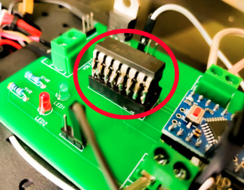
Piggybacking L293D
L293D piggyback configuration is an Easy Way to Double (or in my case triple) The Current as well as the power of L293D Motor Driver IC to drive high torque/ high current motor/ high resistance load. (This strategy should work for any L293D chips). L293D Piggyback is a speedy and simple technique to double the current output to the motor.
![]()
So the entire thought is to solder another L293D chip straightforwardly over the present one. Pin to Pin. This puts the two chips in parallel mode so the voltage will remain the same as before but the current increases. These chips are evaluated at about 600ma constant or up to 1.2A for a brief period. After piggybacking two of them together, they will provide output with 1.2A persistent current and 2.4A for brief periods.
Arduino Pro Mini
This teeny tiny board was developed for applications and projects where space is premium and installations are made permanent.
Small, available in 3.3 V and 5 V versions, powered by ATmega328. Due to its small size, in this project we will be using this board to control Arduino Based Motor Driver Board.
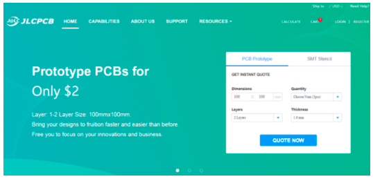
Online PCB Manufacturer – JLCPCB
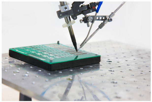
JLCPCB is one of the best Online PCB manufacturing company from where you can order PCBs online without any hassle. The company works 24 hours a day, 7 days a week nonstop. With their high tech machinery and automated work stream, they can manufacture huge quantities of high-class PCBs within hours.
![]()
JLCPCB can develop PCBs of various complexity. They develop Simple and cheap PCBs with Single layer board for hobbyists and enthusiasts as well as complex multi layer board for high standard industrial applications. JLC works with large product manufacturers and may be the PCB of devices you are using such as laptop or mobile phones were made at this factory.
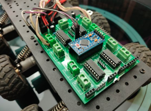
Arduino Motor Shield Board Explained
Features of RootSaid Arduino Motor Shield
- Controls 4 Motors Independently at a time
- Independent Speed Control
- Headers for Connecting Analog/Digital Sensors
- 5 V, 12 V and Gnd Headers for extra components
- Piggybacking without soldering
- Support HC12 Wireless Module
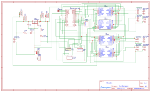
Now let us take a look at the circuit of our motor driver board.
![]()
Looks a bit messy? Don’t worry, I will explain it for you.
The Regulator
The input power is connected to a 7805 regulator. 7805 is a 5V regulator which will convert an input voltage of 7- 32V to a steady 5V DC supply. 5 V supply is connected to voltage...
Read more » -
RC Tracked Robot Using Arduino – Step By Step with PCB Layout
01/03/2020 at 05:07 • 0 commentsRC Tracked Robot Using Arduino – Step By Step with PCB Layout
Introduction
Hey guys, I am back with another cool Robot chassis from BangGood. Hope you have gone through our previous projects – Spinel Crux V1 – The Gesture Controlled Robot, Spinel Crux L2 – Arduino Pick and Place Robot with Robotic Arms and The Badland Brawler which we published last month. Looks cool with under glowing lights right?
![]()
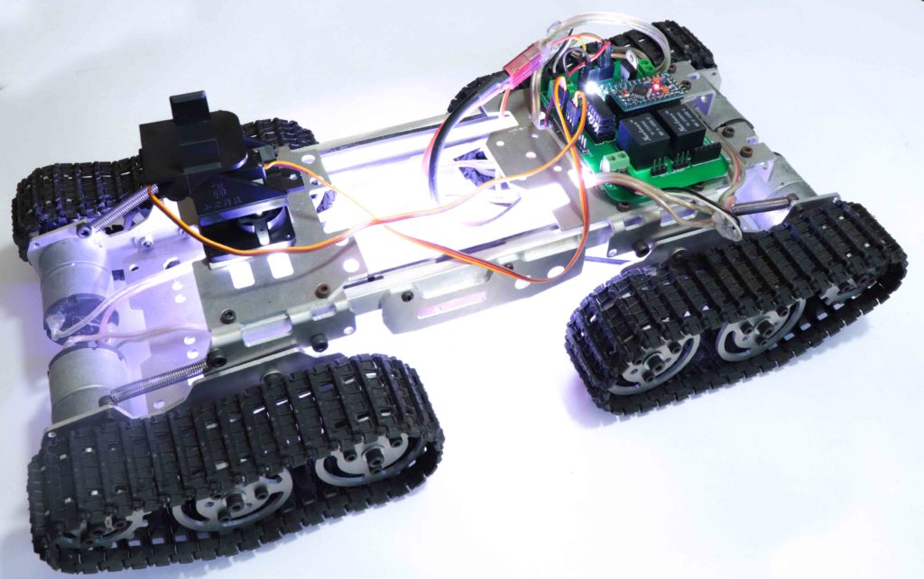
This time I have a rough Terrain Robot with 4 Wheel Drive and dedicated suspension for it to travel over rough terrain. Check it out.
Why not build one for yourself? Here we will learn how to build a Off Road Wireless Multipurpose 4 Wheel Drive Arduino Tracked Robot for a smooth ride over rough terrain – A DIY Rough Terrain Wireless Crawler with Suspension.
We will provide you with the design, code, circuit diagrams and links to buy your own robot kit, chassis and the sensor modules used in this project.
Online PCB Manufacturer – JLCPCB
JLCPCB is one of the best Online PCB manufacturing company from where you can order PCBs online without any hassle. The company works 24 hours a day, 7 days a week nonstop. With their high tech machinery and automated work stream, they can manufacture huge quantities of high-class PCBs within hours.
![]()
JLCPCB can develop PCBs of various complexity. They develop Simple and cheap PCBs with Single layer board for hobbyists and enthusiasts as well as complex multi layer board for high standard industrial applications. JLC works with large product manufacturers and may be the PCB of devices you are using such as laptop or mobile phones were made at this factory.
HC12
![]()
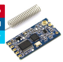
HC 12 is a really cheap long range wireless module which can be used for wireless serial communication over a long distance of upto 1.7 KM. The module is really compact light weight and breadboard friendly which makes this the best wireless controller for our project.
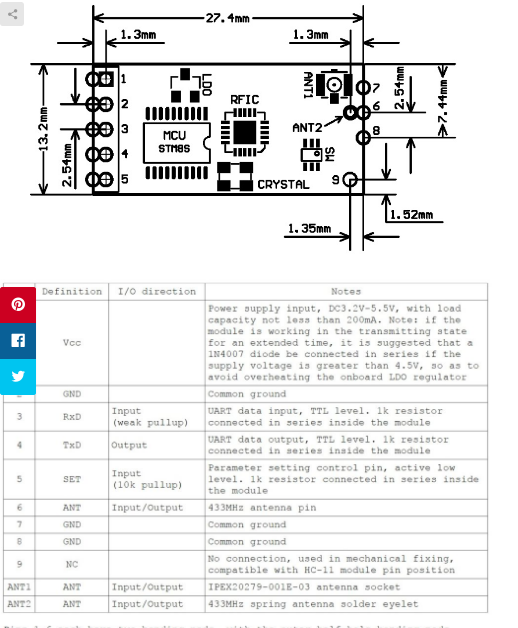
Pinout
![]()
Testing HC12 Connection
#include <SoftwareSerial.h>
SoftwareSerial HC12(10, 11); // HC-12 TX Pin, HC-12 RX Pin
void setup() {
Serial.begin(9600); // Serial port to computer
HC12.begin(9600); // Serial port to HC12
}
void loop() {
while (HC12.available()) { // If HC-12 has data
Serial.write(HC12.read()); // Send the data to Serial monitor
}
while (Serial.available()) { // If Serial monitor has data
HC12.write(Serial.read()); // Send that data to HC-12
}
}
Joystick
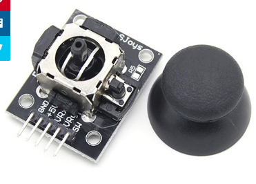
This is the most widely used robotic controller which comes with various robot DIY robot kit/robot arm kit that is built to work with arduino. The design is quite simple and is very easy to use. It uses two potentiometers to calculate the motion in the x axis and y axis and a switch to sense the button press.
![]()
This can be easily connected to the arduino’s analog pins and read analog values directly.
Code for testing the joystick is available down below. Feel free to download/edit it as per your need.
Before uploading the main code, make sure your joystick works by using this code. Download the code from the above link. In this example, what we are doing is simply collecting the data analog outputs from the Joystick using the analog pins (A0, A1,A2) of arduino. These values are stored in the variables and are later printed on the serial monitor
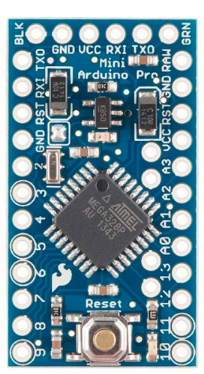
Arduino Pro Mini
![]()
This teeny tiny board was developed for applications and projects where space is premium and installations made permanent.
Small, available in 3.3 V and 5 V versions, powered by ATmega328. Due to its small size, in this project we will be using this board to control Arduino Based Motor Driver Board.
The Robot Chassis
This is the robot chassis I used to make my BLE Robot. I got this kit banggood.com. Not only this one, they have so many types of robot frames, motors and almost all the sensors for doing arduino, raspberry pi and other electronics and hobby projects.
You will get all these things for a cheap price with really fast...
Read more » -
Simple Line Follower Robot using Arduino – Step By Step with PCB Design
01/03/2020 at 05:01 • 0 commentsCreating a Line Follower Robot using Arduino Nano
Well, guys this is one of the project that never gets old. This was the first thing I did when I started learning about Arduino. An Arduino Line Follower Robot – A Line Follower Robot Using Arduino UNO and IR Sensor, which follows a line without user interaction. A small autonomous robot which will “see” and follow the line and take decision when it sees a turn by itself.
New to Robotics?
We have a beginners guide on “Getting Started with Robotics” which will give you a kick start in this field. Check out our free video tutorial below for a brief introduction.
Arduino Line Follower Robot
In this tutorial, we will discuss the working of an Arduino line following robot which will follow a black line in white background and take the correct turn whenever it reaches curves in its path.
Arduino Line Follower Components
- Arduino
- IR Sensor (Array Sensor or 2 Individual Sensors)
- DC Motor
- LIPO Battery
- Robot Chasis
- Arduino IDE
Before jumping into line following robot tutorial, let’s get familiarized with the components used. If you are an expert and familiar with these components you can skip this section and straight away jump to the tutorial and start building Arduino Line Follower.
The Chasis of the Arduino Line Follower Robot
The first thing to do is build a chassis for WiFi Robot using Arduino. You can build it the way you like. The only thing you should keep in mind is, it should have enough space for Arduino, L293D Motor Driver, and a LIPO battery. For our project, I will be using a 12V LiPo Battery. You can use foam board or aluminum sheet or wood piece for building the base. These are some of the best robot chassis available for you to build this project. Check out the link below.
Get the Best Robot Chassis Online
Arduino
You all might be familiar with Arduino; which is the most widely used and fastly evolving electronic platform with so many microcontroller boards and software. For our line following robot, I will be using Arduino UNO which is the most commonly used board. The Arduino Nano is the best option to get started with electronics and coding if this is your first experience with Arduino Platform. You can use any Arduino Board for this project.
IR Sensor
As mentioned earlier, our line following robot will be following a black line in a white background. So we need something that will ‘see’ the line and tell the line follower to follow the line or to turn around if it is going away from the line. For this purpose, we will be using an IR (Infra Red) Sensor.
This IR sensor mainly consists of an IR transmitter (IR LED) and an IR receiver. IR LED always emits IR rays to the direction it is pointing to. When the IR rays hit a surface, some rays will be reflected back depending upon the color of the surface. Means, the brighter the color is, the more IR will be reflected back. Darker the color is, more IR will be absorbed by the surface and lesser IR rays will be reflected back.
![]() These reflected rays are sensed by the IR receiver and depending upon the received IR rays, the resistance of the receiver varies which will, in turn, varies the output voltage. Thus it is possible to sense the color of the surface where the robot is running by looking into the reflected IR rays. So it is very easy to measure how bright the surface is which will make it easy for us to track the line.
These reflected rays are sensed by the IR receiver and depending upon the received IR rays, the resistance of the receiver varies which will, in turn, varies the output voltage. Thus it is possible to sense the color of the surface where the robot is running by looking into the reflected IR rays. So it is very easy to measure how bright the surface is which will make it easy for us to track the line.![]()
There are so many cheap IR sensors available online; you can purchase any of them. You will need at least two of them for making the line follower robot.
H Bridge and L293D Motor Driver
An H-bridge can be any switching circuit using Bipolar Junction Transistors (BJT) or Field Effect Transistors ( MOSFET or MESFET) which allows a voltage to be applied across a DC motor without making physical or hardware changes in the circuit. H Bridge circuits are widely used in the field of robotics to switch the direction of...
Read more »
 These reflected rays are sensed by the IR receiver and depending upon the received IR rays, the resistance of the receiver varies which will, in turn, varies the output voltage. Thus it is possible to sense the color of the surface where the robot is running by looking into the reflected IR rays. So it is very easy to measure how bright the surface is which will make it easy for us to track the line.
 Georgi Angelov
 jareklupinski
 Makarand Kapoor
 Carl Smith
 geekstips
 bhaskar.anil430
 AVR
AVR SHIVANI
 Mathieu Stephan
 Hiroshi Takey
 plugg.ee Labs
 wombatics
 Hackspace Schwerin e.V.
 Bikash Narayan Panda
 Zander Foster