Tim Savage
-
Getting USB master working on a Pi Pico
08/23/2021 at 02:05 • 0 commentsWith the driver from the PC working and all of the buttons, LEDs, encoders and display working the next step is to get the sequencer and DAC side of things going.
This is where I have started running into problems...
The first issue, the interface would partially startup but the micro would crash, suspected this might have been a power issue, and yes adding a separate 5V power supply solved that.
The second issue, when plugged into the micro the Maschine controller doesn't identify as a HID device. This is an issue I've not yet been able to solve. Have used Wireshark to capture all comms when plugged into the PC and the 2 USB Interface descriptors are returned one a custom interface and the second being HID, however connecting to the Pico only the custom interface descriptor is reported. Am at a loss to work out why.
If anybody has more expertise on the behaviour of USB I'd be interested to hear, I have picked up a lot about the ins and outs of USB but there is a lot of details I'm sure I've missed with the breadth of details that go into the protocol. I've also learnt a lot about the TinyUSB stack which may necessitate some contributions to the USB master side of things.
-
Creating the UI
04/06/2021 at 00:13 • 0 commentsNow that I have a display with font rendering and certain effects (eg invert) I can start looking at building a UI.
The UI will make use of the 8-bit line-height to divide the display into 8 rows of text, many queues will be taken from the machines original UI, eg tabs that correspond to the F1-3 keys.
The initial work now provides a scrollable text panel, I've identified the following basic components:
- Tab panel
- List view
- Sequence gridI have already identified some features required in the display rendering from developing components.
Once I have a basic UI working the next step is the sequencer itself. At this point, custom hardware and a switch to embedded development will really be required.
-
More display work
03/30/2021 at 00:15 • 0 commentsFollowing the last post on working out how the display data is formatted, I have come up with a better description of how the data is formatted.
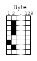
The display is made up of rows, each row is made up of 128 bytes where each byte defines 8 vertical pixels.
![]()
On the Maschine Mikro Mk2 that means that 8 rows (64pixels) are required for the whole display.
In addition, each USB report can send up 256bytes of row data so an entire screen refresh requires 4 reports.
The Report header
After mucking around with the header fields I have managed to determine what each of them do
Field Type Description Address uint8 Display or Message type identifier (0xE0 for the display) Column Offset uint8 A column within a row to insert pixel data - uint8 Possibly a high byte for the previous field for larger displays, set to 0 Row Offset uint8 Row from the top to insert pixel data - uint8 Possibly a high byte for the previous field for larger displays, set to 0 Row Width uint8 Width of each row in pixel data (allows for partial row updates) - uint8 Possibly a high byte for the previous field for larger displays, set to 0 Row Count uint8 Number of rows in pixel data, for a full row this would be 2,
must be at least 1.- uint Possibly a high byte for the previous field for larger displays, set to 0 Following the header is up to 256 bytes of pixel data.
The following rules apply, Row Width x Row Count must be <= 256. So an entire vertical slice of the display can be updated by setting with width to 0x20 and the row count to 0x08.
-
Decoding the display
03/28/2021 at 04:55 • 0 commentsA bit of thought was obviously put into the layout of the display. The display uses 1 bit per pixel but it is broken up into 8 pixel bands where each byte in the display buffer represents 8 vertical pixels with 128 bytes making up a full stripe. This is a clever design as it allows for characters to be easily much easily rendered (as long as they are 8 bits high) and allows for simple updates to small blocks of the display (eg the current time code) without sending the entire display buffer.
I still need to do some investigation of the display header to determine what all of the various fields are used for, I am assuming one will be an offset within the pixel buffer for doing partial updates.
To accommodate this I've added a single file program for converting the output from GIMP's export as C-Header into a pixel buffer that can be rendered to the display.
-
LED testing
03/25/2021 at 06:59 • 0 commentsLooping through all of the LED's for the RGB LEDs (pads + the Group Button) a random colour is generated.
Rusty Maschine
Repurposing a Maschine Mikro Mk2 controller to drive a Microcontroller MIDI sequencer or CV/Trigger outputs (and learn Rust)