 agp.cooper
PIMD V2
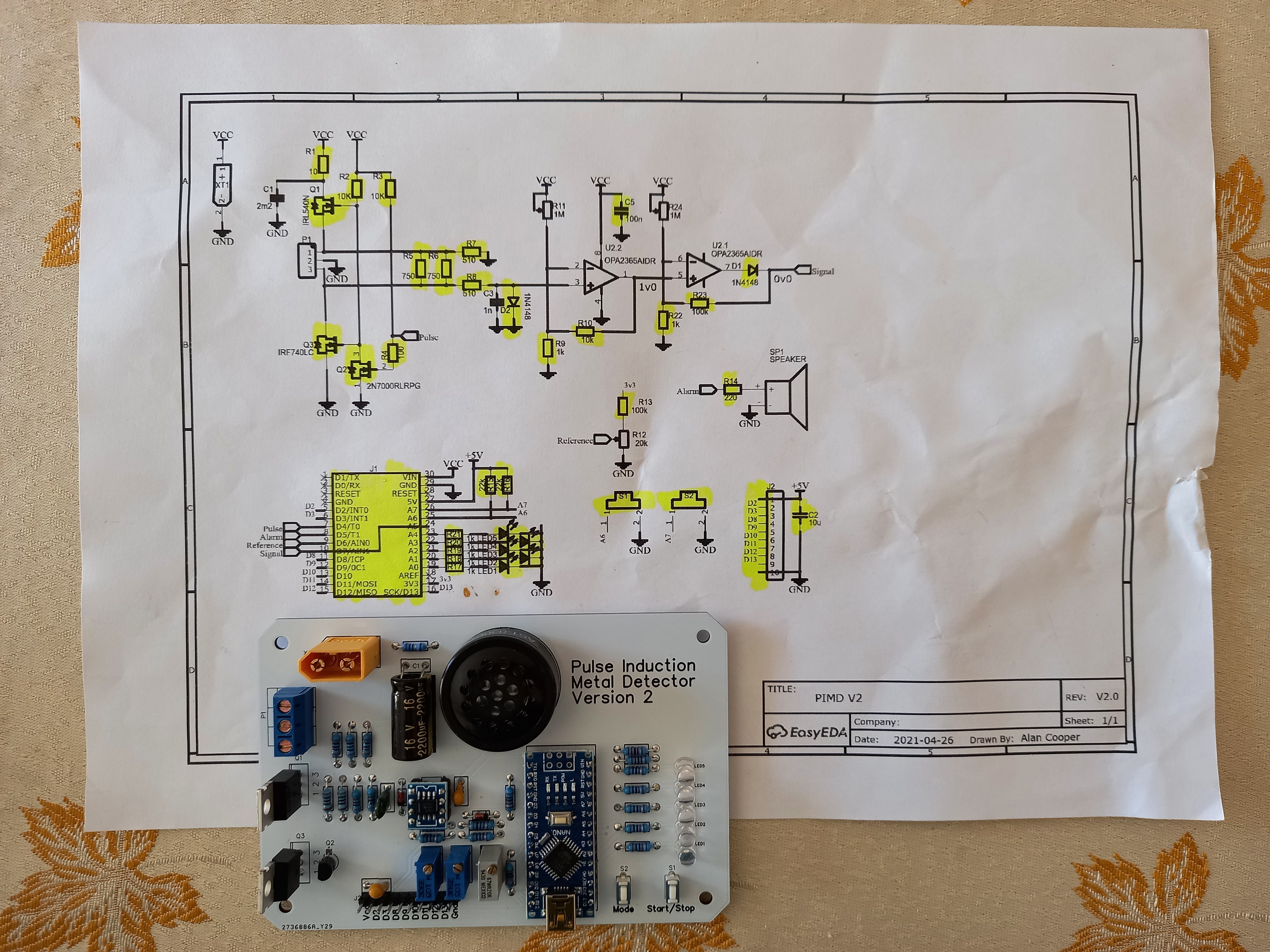
Reworked the schematic to add an OpAmp (OPA2365).
Added A0 to the signal output so I can look alternative signal processing options.
This board uses an IRL540 instead of an IRF540, which reduces the MOSFET voltage drop.
Here is the assembled board before testing:
Two Signal Processing Approaches
ADC
First we could go the ADC route, the board is setup for this.
With a 1MHz clock, we can do samples every 13 to 14 us without losing accuracy.
We can trade faster conversion for accuracy.
Timer
The current approach measures the time the signal takes to decay to a specific test voltage (~40mV).
We could expand the number of voltage tests by controlling the reference voltage using a R-2R resistor ladder. Unfortunately I did not make provision for this with this board.
TBC ...
AlanX
Discussions
Become a Hackaday.io Member
Create an account to leave a comment. Already have an account? Log In.
It's only about 1 bit of accuracy you lose with the 2MHz clock, and you can reach a sub 7us sample time: https://arduino.stackexchange.com/questions/86808/arduino-fast-adc-sampling-which-burst-control-is-best
Are you sure? yes | no