 agp.cooper
Adding Gain
Why do we want to add gain?
In order to increase detection limits we need to increasing the signal to noise ratio (SNR) of the target response. The SNR can be improved by waiting for the coil and ground response to decay.
This works because the target response (for medium to large objects) has a longer time period (decays more slowly). We cannot wait too long or the target signal will be swapped by the noise floor (about 1-2uV).
In general the larger the target the longer the decay time and the longer the time for the optimal SNR measurement.
Therefore, different setting would optimise for small, medium and large objects.
Attempting to filter the coil and ground response would be better for small objects.
Version 2 - PIMD
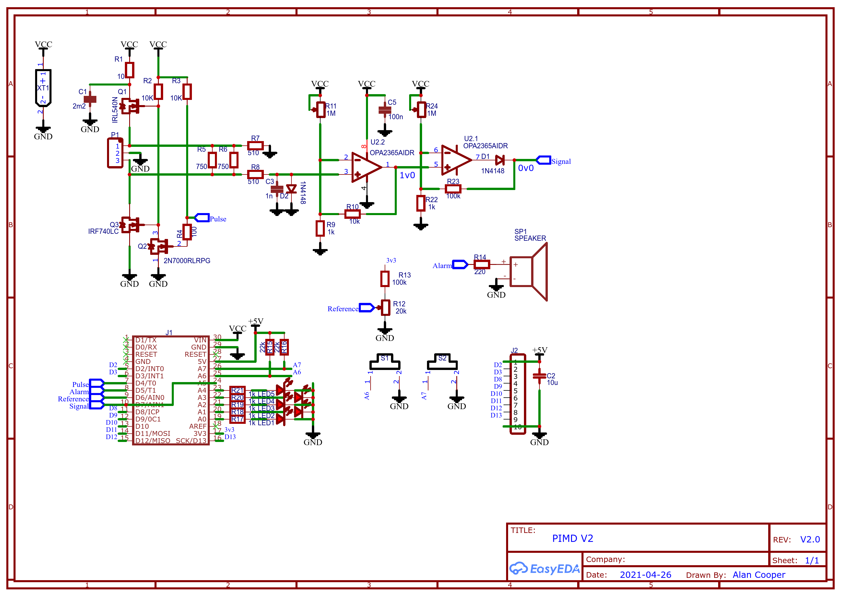
Here is my updated schematic:
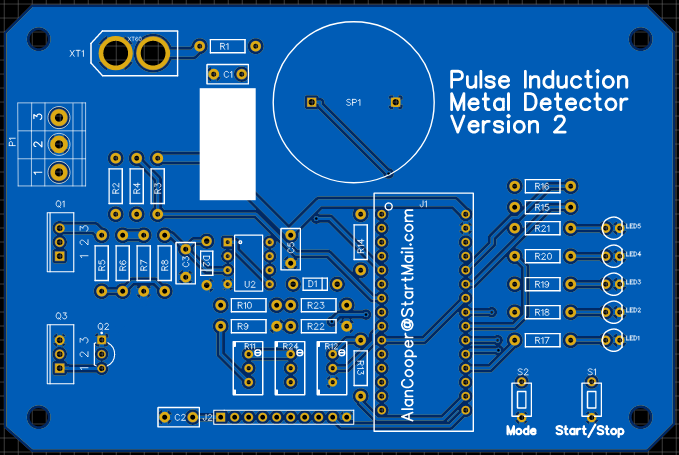
And the PCB:
Note: I have routed the signal to both D7/AIN1 (the comparator negative input) and A5 (an analog input). This allows experimentation with Analog to Digital systems.
Filtering the Coil and Ground Signal.
PIMD Version 1 code cancels the coil and ground signal by subtracting an exponentially smoothed long time constant filter from an exponentially smoothed short time constant filter. Basically hold the coil on the ground until the signal decays away. Now it only responses to changes in the signal (dynamically). It works but we could do better.
It would be nice to give a signal that indicates that the signal curve/shape has changed.
This can be done with the following code:
- Signal=(G0-S0)+(G2-S2)-4*(G1-S1)
- where G0, G1 and G2 are exponentially smoother long term filter values for different sample points.
- and S0, S1 and S2 are exponentially smoother short term filter values for the same "different" sample points.
This works for three voltage or three timer readings, and the formula can be adapted for more than 3 sample points.
AlanX
Discussions
Become a Hackaday.io Member
Create an account to leave a comment. Already have an account? Log In.