 Eric Hertz
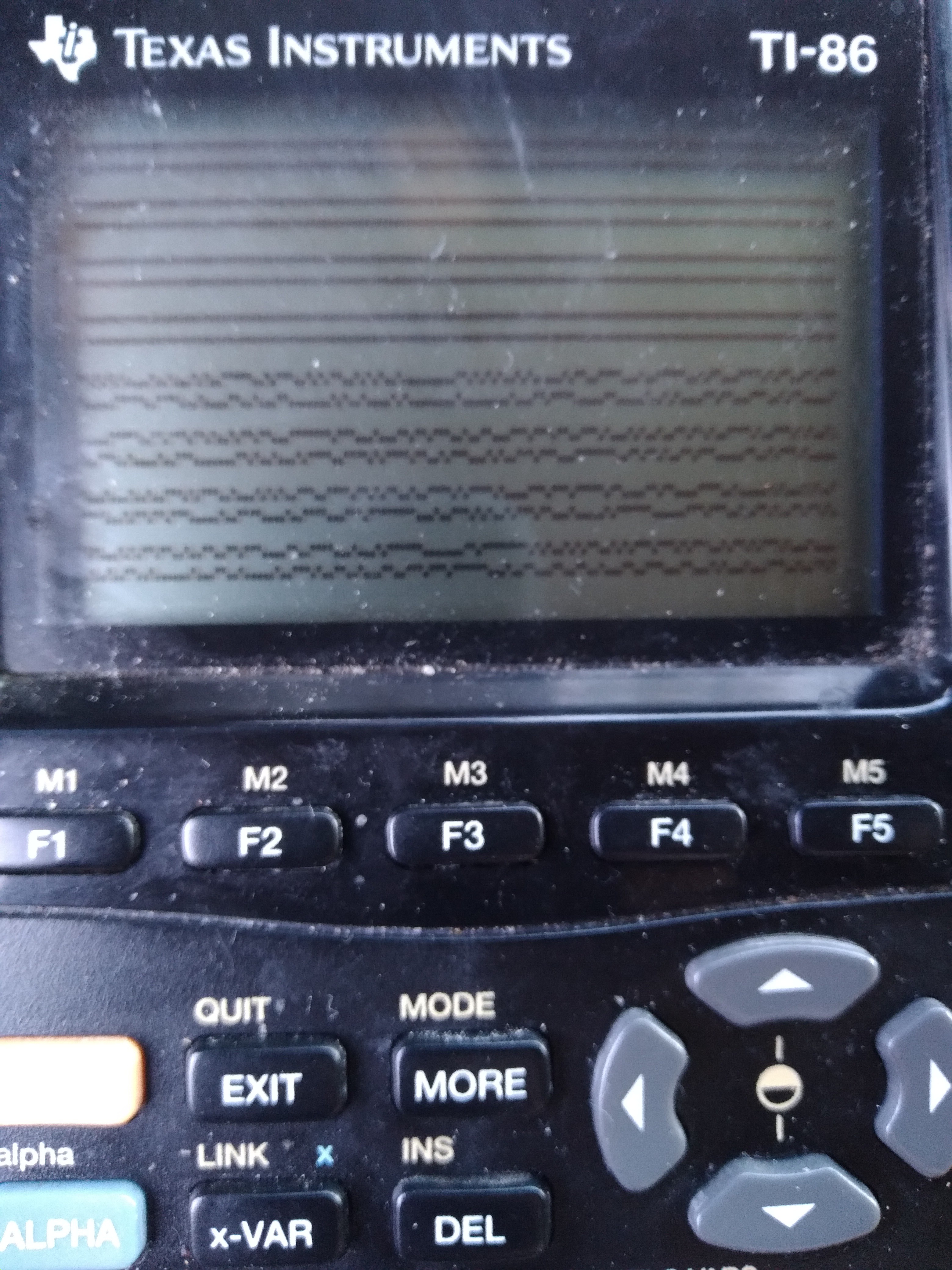
Ok, so it's gnarly-dusty and that's not real sample-data, but here goes:
That's two lines of sample-data, from the link-port, wrapping, to show as much as reasonably-viewable (1024x2 Samples visible).
Presently, I think each sample (pixel) is around 6us... that's about as fast as I could code it, with more than 256 samples.
...
I'm planning to view a signal that toggles at a minimum of 8us, so it's going to have some ugly aliasing(? stretching, anyhow)-effects, but I /think/ I can work with it... in post-processing.
.
This brings me to the link-cable... I've got the "For Windows Only" graphlink (aka "blacklink") from TI, which is actually quite "dumb", as in it doesn't do anything except level-shifting to make the TI-link protocol work with RS-232 voltages, and vice-versa.
I broke out its schematic a while-back in a past log. https://hackaday.io/project/179772-vintage-z80-palmtop-compy-hackery/log/194140-blacklink-cable-schematic
It's really quite simple, using comparators with open-collector outputs and pull-up resistors in both directions. It doesn't even invert the logic levels (which would've been more per the RS-232 standard, but this is /hardly/ RS-232 compliant, thus "Windows only"), which works in my favor.
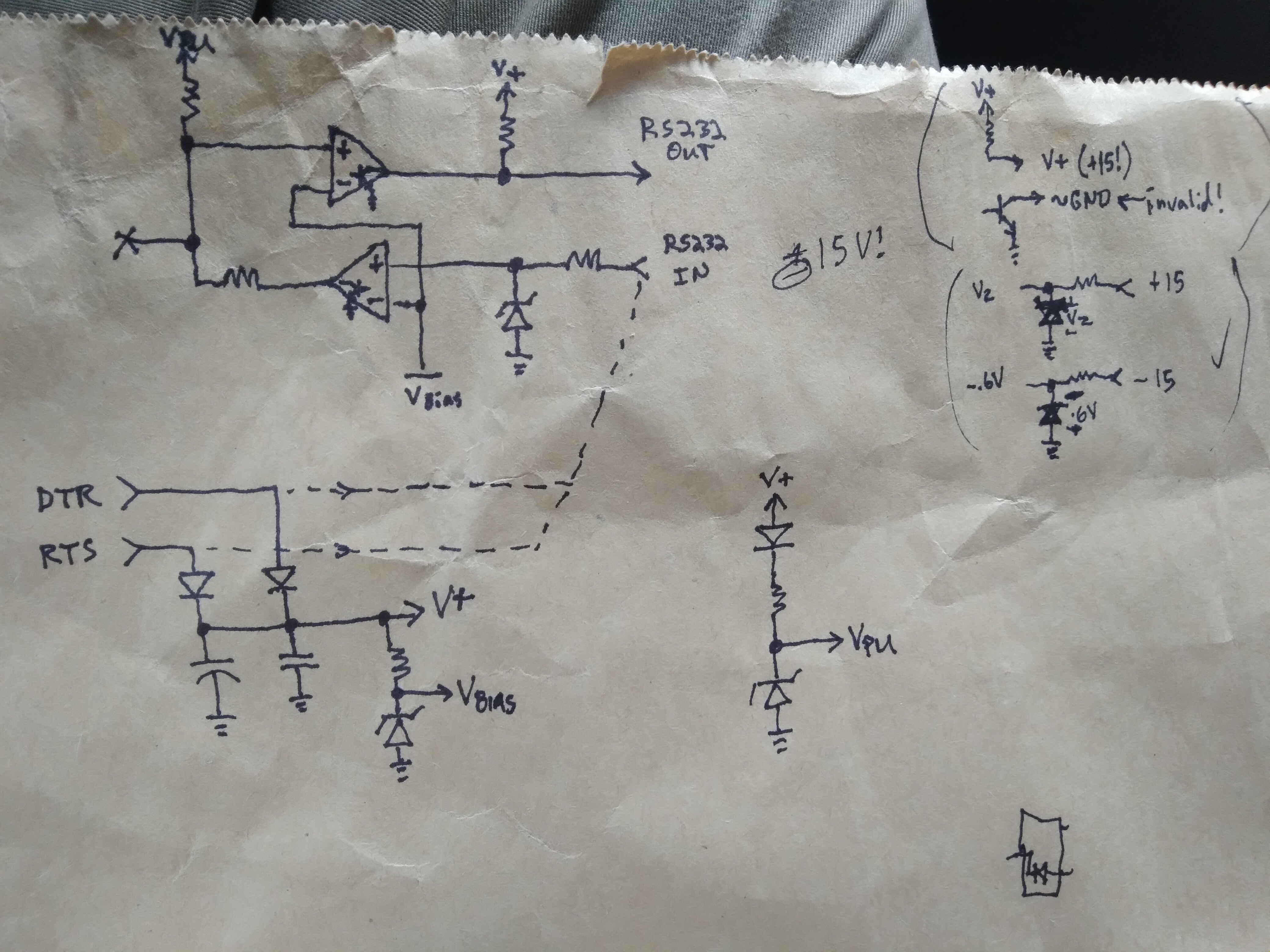
Vbias zener ~=1.6V sets the low<->high threshold for both directions. A pretty decent threshold for most logic-levels.
Vpu zener regulates the TI link to 5V (if available) or drops-out due to the other diode, allowing the calculator to do the pulling-up to closer to 5V (a little gnarly with the voltage-divider between the two TI-Link outputs' pull-not-up-but-to-each-other, better look into that).
Basically, what we have here is a logic level-shifter which is pretty durn easy to interface with various logic levels...
Or, in this case, since my source signal is 5V logic, pretty much matching the TI-86 link port, a handy little isolator... just in case. I mean, it's not /isolated/ per se, but at least it's not feeding my alleged 5V signal (which may well be higher, since I measured ~4.6V with a multimeter while data was flowing) /directly/ into my calculator's CPU.
... handy.
I've [ab]used it a couple times, now, like this...
The prior case was with my UARtoT software... I had (and used) several options, including wiring the link port directly to the 3.3V-level Tx/Rx signals broken-out from my USB-Serial dongle (as opposed to the RS-232-level signals at the DB-9, which are level-shifted by an HIN213, kinda like a MAX232). I was able to get away with that because long ago I added my own zener-regulators to its signals.
BUT. I could've just-as-well used (and did) the blacklink wired to those 3.3V signals, because... the comparators work down to 2V, have open-collector outputs, and diodes prevent things like Vpu being too low from interfering. And, though, if driven at 3.3V, it won't be able to pull up the TI link to 5V, the calculator does that.
So, frankly, it's really quite handy as a general-purpose TI-Link-to-anything level-shifter + 2.5mm three-connector (kinda rare) phone-plug breakout + input/output separator.
And, frankly, it could easily be recreated from common parts... the /least/ common, maybe, being that 2.5mm connector!
.......
Looks like I may also be using it with 7V logic (Wha?!). Gotta get myself a 7V source for that, heh.
.....
I haven't figured out enough of TI-OS to maximize the number of samples; the sampling routine can do up to 64k, but of course, without remapping during sampling, which'd slow it down, the absolute limit is just shy of 48k...
The key factor, of course, is that of reading each sample into its own byte. Memory-wasteful, but computationally fast, for the highest sample rate possible (~140KSps).
So, since I've touched on this rabbithole... Lessee, the z80-VLSI (Toshiba T6A43) doesn't seem to have a means to remap addresses 0xC000-0xFFFF. They're stuck at RAM page 0. I gather that's not just a software limitation. 0x8000-0xBFFF is the remappable "RAM" page. So, obviously, if we can find an empty page of RAM, we could map 16K there. Addresses 0x4000-0x7FFF is the remappable "ROM" page. But, the fact is, for both these remappable pages, anything that's wired to the T6A43's memory bus can be mapped-in to either of these locations. So, if we can find a second empty RAM page, that'd give another 16K. That'd be the 48K absolute limit, since, like RAM page 0 being permanently stuck at the upper 16K, ROM page 0 is stuck at the lower, 0x0000-0x3FFF.
This has all been pretty well-established already.
For some reason, my mind's on the challenge of maximizing this. Not that I necessarily need to.
Would it be possible to /move/ darn-near /everything/ out of RAM page 0, to a temporary location, then use that space as consecutive memory following whatever page is mapped at 0x8000? Why not?
Interrupts-disabled, and careful selection of instructions... No TI-OS ROM calls, No pushing/popping. I think it could. The screen might get garbled (though, it too can be remapped, haven't really looked into those details). Otherwise, why not?
The last bit is the code executing the actual sampling, /and/ a little bit of code to return things back normalish-enough to restore at least the immediately-necessary parts of RAM page 0 (_asm_exec_ram first, maybe)
Hmmm.... nearly 48KB for a program's immediate/consecutive use... (no intermediate remapping)
Of course, doing this requires finding three empty RAM pages... I dunno enough about TI-OS to do this. Though, I did get a brief glimpse at the variable system, and I think I recall they can be up to 64kb(!). So, creating a variable to contain this would have to be within the OS-calls, but accessing it doesn't. I /think/ creating a 64K variable would assure that wherever it starts (surely /not/ at a page-beginning) there would be three consecutive full pages within it, yeah?
Oh, actually, we only need /two/ full consecutive pages, since the third would be temporarily (mapped-consecutively) in RAM page 0... so, a little math /before/ and /after/ sampling (not /during/) and we don't need a variable larger than 48K!
Anyhow...
Other thoughts:
if I'm only doing 1024 samples, (as I am, now) they could go straight to the frame-buffer, then it could be post-processed. Could be kinda interesting to watch that process.
...
What about remapping /during/ sampling?
In order to make samples evenly-spaced, I had to throw in some nops...
NextSDelayed:
          ;4+7+16+12=39T
 nop       ;4T
 and $ff   ;7T, NOPish
NextSQuick:
          ;16+7+4+12=39T
 ini       ;16T
    ;~= in (hl),(c)
    ;   inc hl
    ;   dec b
 jr nz, nextSDelayed ;12/7T
 dec d     ;4T
 jr nz, nextSQuick   ;12T
But that's 11 unused T-states 255/256 of the time! I wonder if I could throw something in there to be useful... For instance, remapping the "RAM" page is done by simply 'out 6,a'... and I can't see anything wrong with remapping the same mapping repeatedly. So, maybe instead of nop I out6,a... repeatedly. Then, somehow I just need to increment a /once in a while/...
This might be hard to do in 7Tstates, but the idea's there: maybe that unused time could be a bit of a state-machine...
It doesn't matter what order the samples are stored, they can be reordered in post-processing. So, e.g. where the remapping occurs within the sampling doesn't really matter... maybe the remapping occurs (a gets incremented) during the 7th sample after every 16K... then, start hl seven short of the intended destination.... ahh, but wait! hl doesn't wrap at 16k... so maybe we need another state in that state machine to AND h, $3f... and maybe that occurs two samples before the remap/inc a, heh... it could get ugly. But, it's another plausibility to ponder, which I'm sure my brain won't get off for several hours. Even though, realistically, I should only need, oh, roughly 8*3*8*13/6= heh, a measly 416 samples...
Weee!
...
Not so smart: Graphlink as a level-shifter is only one-way for each wire... and, ultimately I'm looking to send data on the same wire. That's OK... just hook up one wire as an input and the other as an output, and we've reverse-Charliplexed one wire to four GPIOs ;)
...
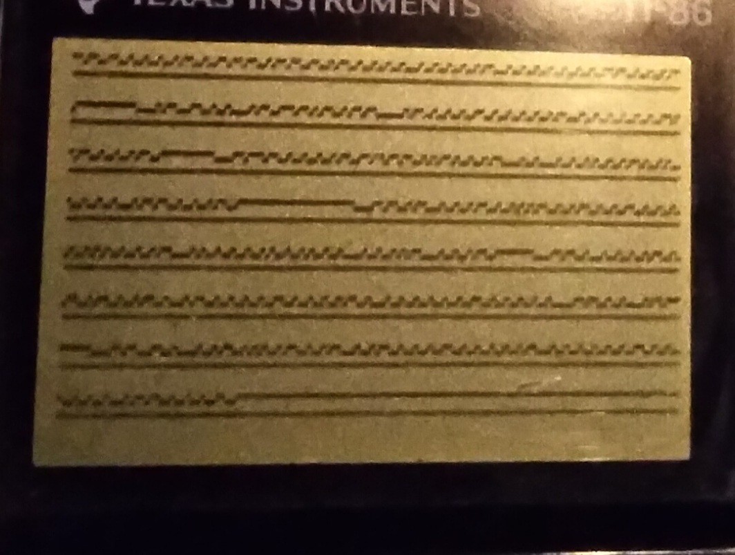
THIS, however, just doesn't quite look right to me. First-off, it's surely harder to view at 6us samples of 8us data... and that is presuming the calc is actually running near 6MHz... but, there be some long 1's and zeros that don't fit the spec I read. Is it possible the calc is running that slow that it's sampling /slower/ than 8us? Most of it looks about right, though... hmmm...
Further, it's allegedly a protocol that only talks when requested, but clearly that's not the case! It's also alleged (by another source, though only the one) this link /may/ be used for internal communication, while another for request/response... which is prb better, but that one is a different protocol, which means I'd be programming the protocol and requests "bindly." Heh.
And, frankly, I can't figure out what [sub]systems could possibly be intercommunicating via this link... I've looked at many schematics, there's allegedly only one "smart" device in this system, all the sensors I've seen are analog!
Guess I may learn a thing or two...
Or maybe this link is like "dmesg", heh! That'd be /kinda/ awesome, except then I think I'd need a bigger screen, /if/ I could figure out how to decode it.
....
Been working on a screen-cap system so I can analyze at the pixel-level over an extended period without draining the batteries... dunno how, was supposed to be very straightforward, but i managed to crash TI-OS pretty hard, twice!
Anyhow, analyzing that photo again just a second ago, it occurs to me those extended lows look about the same length as those that follow the long highs/idle. The latter are bus-takeover-requests, the highs being idle. The former, then, similarly-lengthed-lows /without/ a prior idle might just be an immediate response from a previously-non-sending device.
That makes a lot of sense.
Discussions
Become a Hackaday.io Member
Create an account to leave a comment. Already have an account? Log In.