Andy
AndyOver the last months I’ve made a lot of changes to my motion control system. Almost all mechanical components have been replaced and its capabilities have been vastly extended, including the ability to continuously rotate and home it for repeatability.
Details
Mechanics
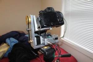
To implement the new features I had to remodel and reprint all 3d printed parts. To minimize the printing times I implemented all changes manually first. After drilling, sanding and glueing my modifications into the current model I was ready to model the new hardware. An overall goal here was to make components which might get replaced in the future modular.
I equipped the base with a cable channel to route the cables from the cable chain into the base where they are plugged into an adapter PCB. I also attached an optical endstop to the base to enable homing for this axis while keeping the possibility to continuously rotate.
The pan head has been modified the most. I added a mount for the rotary connector, which is a 12 channel slip ring connector from Senring, and a pin to engage with the endstop in the base. The back has been completely removed to make the gimbal slimmer and save material and printing time. To retain stability I added ribs on the back and Metal brackets on both sides. The top of the pan head has the same optical endstop as the base attached to it, to zero in the tilt motion.
The camera mount now has a cutout which holds the macro rail to prevent it from rotating and also a pin to engage the endstop on the pan head. The macro rail has been replaced with one that doesn’t suck and allows for easier mounting of the camera because the base plate can be removed. It also features a longer knob to tighten the plate which is easier to access while the camera is attached to it.
The rotary connector in the pan axis allows me to continuously rotate the rig without twisting the cables. The connection is stable enough to feed the motor connections of the steppers, as well as the endstop signals and supplies through it. The tilt axis will get such a connector in the future to allow for connections to the camera, from where I can supply it with power and trigger the recording.
Electronics
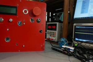
The Electronics also underwent some changes. The Ghetto-style Tupperware container is gutted and gone. Everything is now on one stack on the Raspberry PI and mounted to a new end piece of the slider. The Arduino Mega has been replaced with an Arduino Uno as this version of my motion control rig will not utilize more than 3 axes onboard. A power converter also fits onboard which powers the Arduino as well as the Raspberry Pi. This makes the only external component the 12V power brick.
The endstops were straightforward to implement. For the mechanical Endstops I just had to connect the “normally closed” and the “common” pin to the endstop header of the arduino. In the grbl settings I configured the axis accordingly and was done. The optical endstops were just as simple, except they also needed a supply voltage.
To make the gimbal detachable from the slider base I added an adapter PCB inside the base. The cables from the cable chain and from the gimbal are plugged into the PCB as well as the endstop cables of the pan axis.
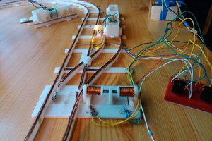
When I connected the steppers to the rotary connector I ran into a problem. The motors only stuttered when I tried to move them. I measured the resistance of the connector as 3 Ohms. The stepper measured at about 5 Ohms. I figured most of the Voltage was lost in the connector and I had to do something.
Well, what I definitely did not do was:
- design a stepper driver backpack to mount the driver directly to the backside of the stepper,
- have the design manufactured in china and shipped to me,
- realize that I made the holes for the screw terminal too small,
- correct the mistake and order a new batch,
- assembly and test the PCB,
- only to stumble across the actual issue which was...
 Szabolcs Lőrincz