 Anaveo Labs
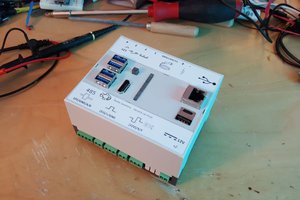
Glo includes:
- 4 addressable RGB LED channels
- 1x Digital pin (D2), 8x Analog Pins (A0-A7), and Serial Transmission Pins (TX & RX). However, analog pins may be used as digital pins if necessary. These can be used to wire up other sensors and modules.
- 3x GND pins, 2x 5V pins, 2x 3.3V pins, 1x VIN (voltage supplied by power supply) pin, and 1x RESET pin.
- Open source Arduino-compatible microcontroller (Atmega 328p)
- FT232 USB to Serial converter chip. This chip is used on official Arduino boards and does not contain driver issues commonly found in clones (devices using the CH340G chip).
- Advanced Monolithic Systems AMS1117 Voltage Regulator for microcontroller
- Hall effect sensor. This sensor detects the presence of nearby magnets. For example, this allows for rotation based patterns if Glo is mounted on a bicycle tire.
- Mini USB serial programming port
- Power and status LEDs
- Mini USB 5V power port and terminal block 5-12V power port. Useful for 12V 3pin addressable LEDs
- A 1 amp thermal fuse has been added to the USB Power Port. This is a safety feature meant to prevent damage to your USB power supply as most USB devices have a maximum current tolerance of 1 amp. In the case that more than 1 amp is drawn from your USB port, the fuse will open the circuit and will reset itself when less than an amp is drawn. If you would like to bypass the fuse, you can remove it by desoldering the component (marked F1) or soldering a jumper connecting the component's two leads together.
Glo can safely control up to 240 individual LEDs, or 60 LEDs per channel. This allows for control of:
- 26 feet/8 meters of low-density strips (30 LEDs per meter)
- 13 feet/4 meters of medium-density strips (60 LEDs per meter)
- 5.5 feet/1.6 meters of high-density strips (144 LEDs per meter)
 gary olzeke
 Nick Sayer
 Lauri Pirttiaho