 zaphod
In the last update I got the clock ticking, but it was not doing so accurately (I was able to notice it lose a half hour over the course of a couple days), and the firmware/verilog running on it was a bit of a mess
the first order of business was cleaning up the code repo. This was just some organization and some simple changes to the verilog top level to get it to work on the new FPGA. As part of this clean up I added UART support to the device's firmware, so now it blasts the number of seconds since it was powered up (I call this the clock's epoch (i.e. like the unix epoch)) out over the UART. I also added a software directory and some host side python scripts to allow me to calibrate the clock.
Specifically I wrote two scripts:
- z_1_rtc_host.py
- plot_error.py
z_1_rtc_host.py counts the number of seconds that the clock has accumulated or lost since the program was started. It works by comparing the clock's internal epoch to the unix time stamp reported by my computer (since the clock starts at 0 when you power it up the script normalizes both time stamps to the t=0 being the time that the program started). The output of the script is just a simple .csv with one column showing how long the measurement has been running for, and the other showing how many seconds the clock has lost (negative number), or accumulated (positive number).
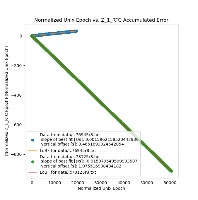
plot_error.py just plots the .csv file with the number of seconds (according to my computer) that the experiment ran for as the independent variable. With no tuning I got a graph that looked like this:

This image is mostly pretty bad, after ~60kSec the clock was ~900Sec slow, or in other words it lost about 15 minutes in only 16.66 hours, which is far from usable. This is a deviation of about 1.5%. That being said, the graph is very linear, which means that the observed error is systematic, and can therefore be calibrated out, at least in theory.
I went ahead and calculated a corrected master frequency based on the slope of the line in the last image, and replaced the nominal OCXO master frequency with the calculated OCXO master frequency in the main divider module, and reran the experiment:
Obviously this is a lot better, but not perfect. Now the clock is running ~0.15% fast, so in the ~22kSec I ran the second experiment for the clock still manged to pick up ~33Sec, or about half a minute in just over 6 hours. Still not usable. While the observed error is still linear, and can therefore be corrected for I figured that it was probably indicating an underlying flaw in the verilog responsible for counting the pulses coming from the master oscillator.
So, after some messing around I went back to my initial simulations and was able to spot a doozy of a bug. IDK how I missed it the first time around, but here it is:
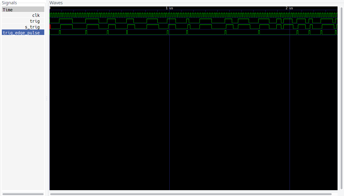
this is the output of the divider test bench (link), showing the signals responsible for synchronizing the master oscillator to the FPGA's internal clock, and then producing a single clock pulse that can be used to increment the counting logic. Basically trig is the master oscillator, and trig_edge_pulse should be a one FPGA clock pulse that corresponds to the rising edge of the master oscillator, however, if you look just before the 1us (and 2us) mark you can see that trig_edge_pulse is missing a master oscillator edge! this is bad news!
(notes:
- the simulation time base is arbitrary, so 1us is not a real time
- the simulation shows trig as irregular, and clk (as well as all clk referenced signals) as regular, in practice this is reversed, the FPGA clk is irregular and the master oscillator is regular, but writing simulations with an irregular clk is annoying.
)
It seems like the error occurs only when the the external trigger coincides with the rising edge of the FPGA clk. Thus the solution was to add another synchronization step as follows:
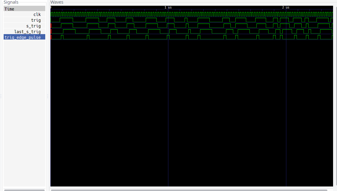
here we see that there is a trig_edge_pulse on every rising edge of the trigger signal!
But the real proof of a squashed bug is in the real world, so here's a measurement with the patched verilog and the initial values for divider frequency:

and as you can see the clock is dead on accurate. In ~80kSec it did not gain or lose a single second, which is almost a whole day without any observable error!
Unfortunately, this means that I'm going to have a hard time telling just how accurate the clock actually is, unless I want to take a really long measurement. For example, the accuracy I'm trying to beat is +/- 1sec/30day (what Casio rates most of their wristwatches to), or ~3.85e-7. In practical terms this means that I would have to run the clock for at least a month continuously in order to observe any error since I can only measure to a precision of one second. This is compounded by the fact that my computer clock, despite being synchronized to NTP, will inevitably have some error and if it is on the order of 1 sec/month then I may not be able to observe any error in my clock. Thus in order to get a reliable measurement demonstrating accuracy better than 1sec/month I would have to run an experiment for much longer than a month. Or, I need more than 1 second precision in my measurement setup.
Nonetheless, these are very encouraging results. They demonstrate that the clock is certainly 'usabely accurate', and is quite likely as good as or better than 1sec/month.
Notes:
some notes that didn't fit into the rest of the post.
first note:
since the process of comparing the unix timestamp to the clock is not synchronized with the clock's ticking you can sometimes get +/- 1 sec of observed instantaneous error, e.g:
- computer checks unix time stamp, gets value of 1000, which is what the clock is displaying,
- clock ticks over, and displays value of 1001
- computer checks clock time stamp, gets value of 1001 (meanwhile the unix time stamp has rolled over at somepoint)
- calculates error as 1001-1000=+1 sec
the upshot of this is that as the clock drifts the graphs show overlaping regions of error, that appear as a thick line in the zoomed out graphs above. If you zoom on them in it looks like this:
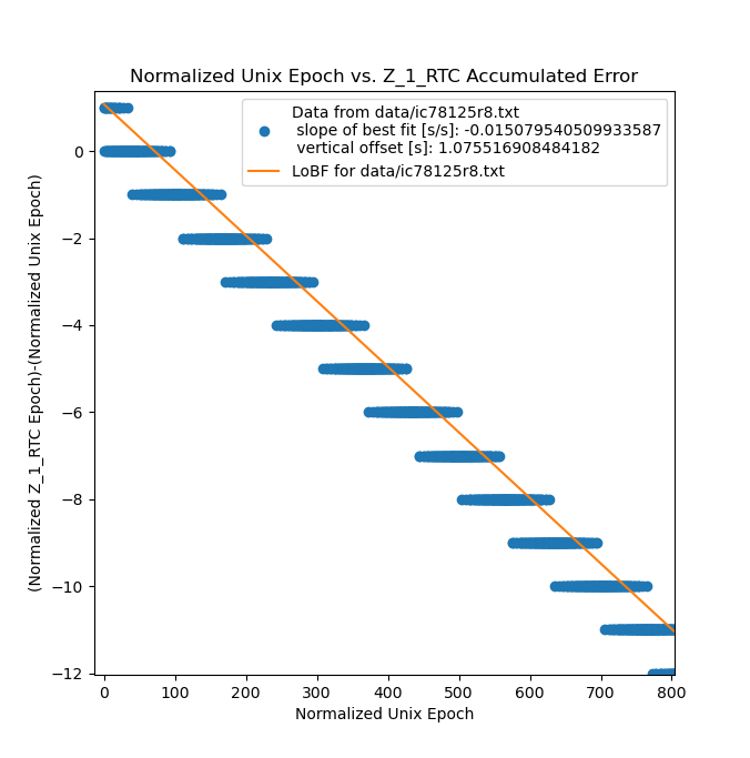
that's also why the calculated slope of the error after I fixed the bug was something on the order of 5e-8 instead of just 0 (as discussed above, my setup wasn't running long enough to detect errors of this magnitude)
second note:
the maximum theoretical accuracy for the clock is limited by the accuracy of the crystal. Part number: OX4150A-D3-1-20.000-3.3-7. Naively adding freq calibration and stability numbers (ignoring aging), gives a number of +\- 107ppb or 1.07e-7 or a little under four times better than a Casio watch. In practice, probably only about as good as a Casio watch.
Discussions
Become a Hackaday.io Member
Create an account to leave a comment. Already have an account? Log In.