deʃhipu
-
Another Workshop
03/15/2023 at 23:18 • 0 commentsWe barely finished one workshop, and we soon are going to have another one! In less than two weeks at Berlin, during the Hackaday conference, we are going to be building another 10 Fluffbug robots. You can read the announcement and buy the tickets here: https://hackaday.com/2023/03/14/hackaday-berlin-the-badge-workshops-and-lightning-talks/
Unfortunately, there are only 10 kits, because I only have one truckload of servos at hand, and ordering more would take much more time than we have left, plus I still have to bring them all to Berlin somehow, and I can fit only so much in my luggage.
But worry not, all the design files and all the code are available in the repository, and you can easily build your own at home. Chances are it will be even less expensive than the workshop kit, because you won't have to pay for express shipping of the parts, and the packages probably be below the tax limit.
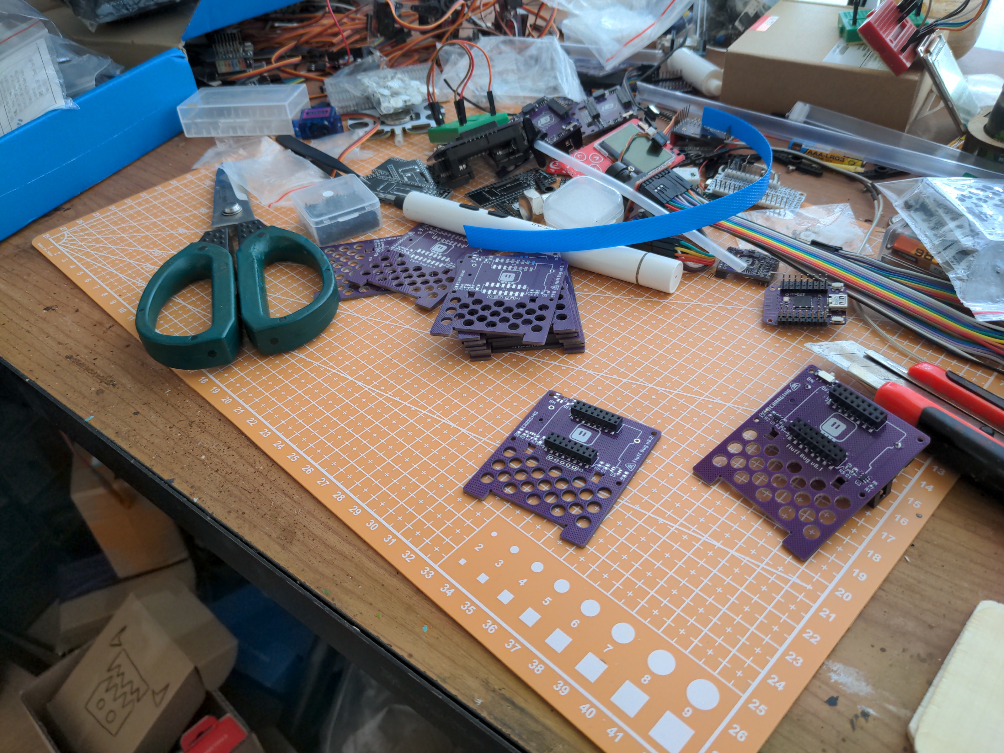
In the mean time, I'm soldering up the kits.
![]()
-
After the Workshop
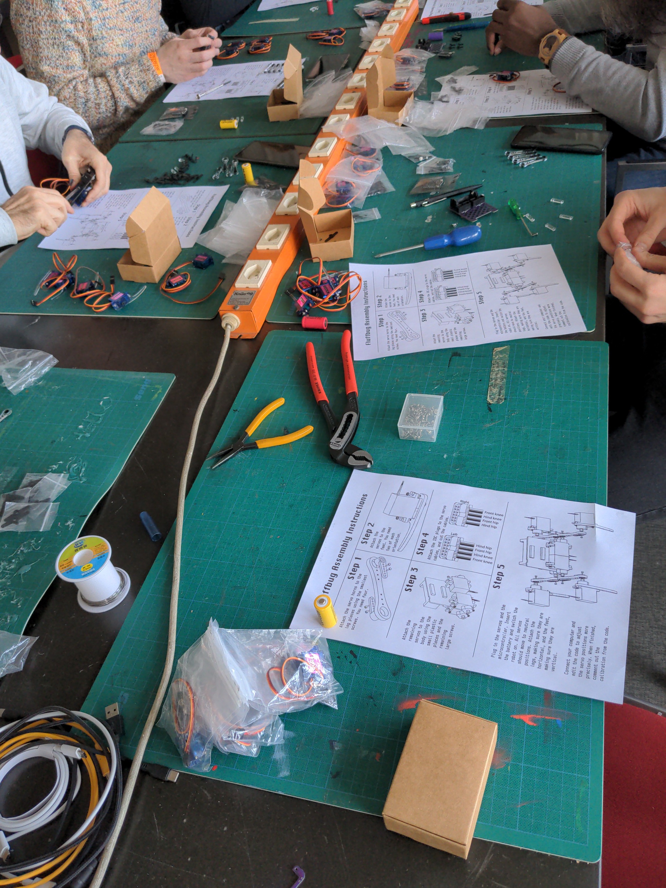
03/05/2023 at 20:25 • 1 commentAs I wrote previously, we just had a small workshop at a local art festival for building Fluffbug robots. I think it generally went very well: all the participants left with working robots, and they didn't seem to have regretted spending those four hours there. I call it a win.
![]()
However, there is always some room for improvement, so I'm going to put some notes here.
Duration
Four hours seems to be the perfect length of the workshop. There was one person who came 2 hours late, and while they did finish their robot, they had to hurry and it didn't come out as good as it could have. And that is without the soldering part – I chickened at the last moment and soldered up all the pins for the participants, because the soldering irons we were going to have available weren't that great. With soldering, it would probably take half an hour to one hour longer.
There are ways in which I could speed it up a little by providing some partially assembled components, but that feels like taking away the fun, so I think I will stick to four hours in the future.
As an aside, we did have a break planned in the middle, but nobody wanted to take it. They were too engrossed in the building.
Tools
I have to bring good screwdrivers, preferably in two sizes, for the tiny screws and for the servo screws. Many people were frustrated using the sub-premium screwdrivers available at the hackerspace. I see myself in a tool shop in the near future.
All the other tools, like wire cutters, pliers and scissors were only needed for a moment and were easily shared. We didn't do soldering, so no soldering irons. I might consider bringing some cork coasters, so people can use them when screwing the screws in and not damage the tables.
Calibration
I definitely need to add LED signalling to the calibration process, so you can be sure when all the servos have updated. This version of CircuitPython takes some random delay before it resets (a mitigation for a number of bugs), so it was frustrating changing the calibration values and than waiting not being sure if it updated yet or not.
I was afraid the people would struggle with the process or find it tiresome, but it doesn't seem they did. Not everyone had a computer, but people did the calibration for those without computers on theirs, so there was no problem with that.
IDC Connectors
As expected, the IDC connectors were the source of the most problems, and also the most scary part of the whole assembly. It's easy to introduce a short if the cables are not perfectly aligned while crimping the connector, and then the robot just stands there, because the battery protection chip cuts the power. It's better than releasing the magical blue smoke, of course, but here again a LED indicator for the calibration process would help a lot, to at least see if there is power.
Getting the right lengths of the cables was a problem as well, as people were understandably afraid of cutting them too short. I think I should prepare some kind of a jig, where you insert the servos at one end, and the connectors at the other, which would give you the right lengths of the cables and also keep the cables aligned. I need to think about how to do it, but probably laser-cutting something will work.
I'm also considering cutting and crimping the cables beforehand, to eliminate this step completely, but I'm not sure I want to do it: it's a lot of work, and it steals some of the experience from the participants – even if it's scary. I will see if a jig makes things easier.
Spare Parts
The most important lesson is to always bring spare parts for the kits. People lose screws, break the plastic parts, damage the IDC connectors trying to re-crimp them, and even strip the gears on the servos. I had two boxes of extra screws, a set of extra leg parts, a bag of ten additional connectors, an additional battery and an additional microcontroller board, and we have used all of those, and without them someone's robot wouldn't be working anymore. Unfortunately I didn't have spare servos, because I'm tight with them (I did plan to have spare servos, but one of the packages I ordered only had 2/3 of the servos I ordered), but maybe next time I will try to find some spares too.
Assembly Instructions
I also got some feedback for changes in the assembly instructions, so I will be adding those. It's mostly clarifications, though. I still can't think of a better way of describing the IDC connector step more clearly, perhaps the jig will help.
-
Bits'n'Bolts Robot Workshop
02/20/2023 at 14:48 • 0 commentsI might have mentioned this already, we are preparing a workshop here in Zürich for building a bunch of Fluffbug robots: https://www.bitsnbolts.ch/programm/fluffbug-robot-workshop. You have to register, because the number of places is limited, and you also have to pay for the workshop separately from the the main event, but I hope it will be worth it.
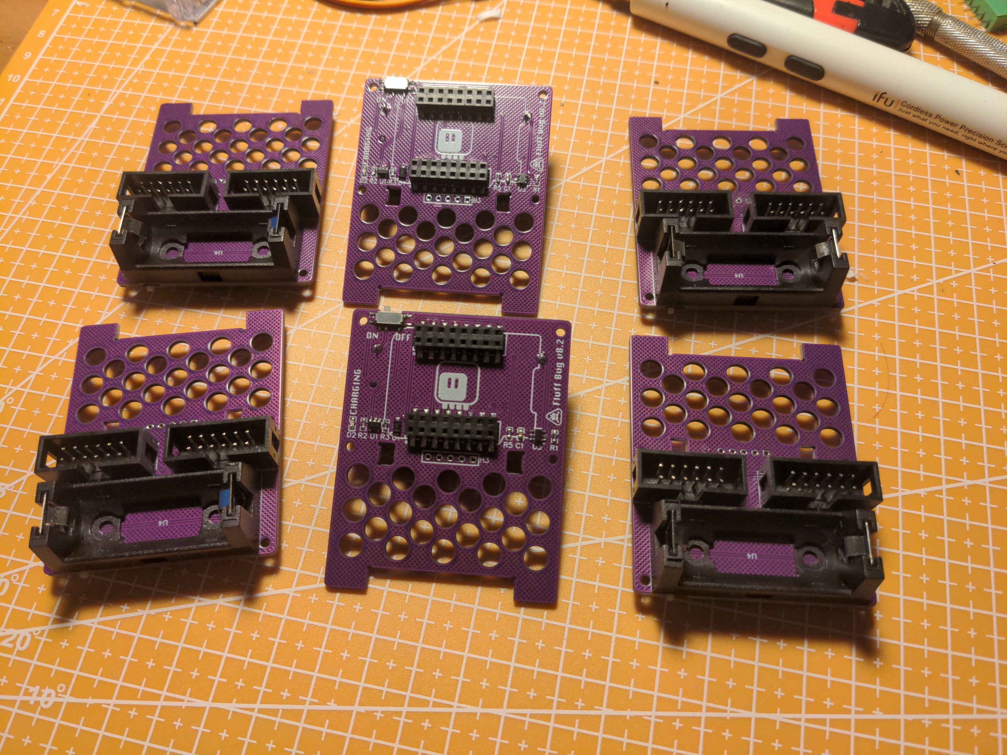
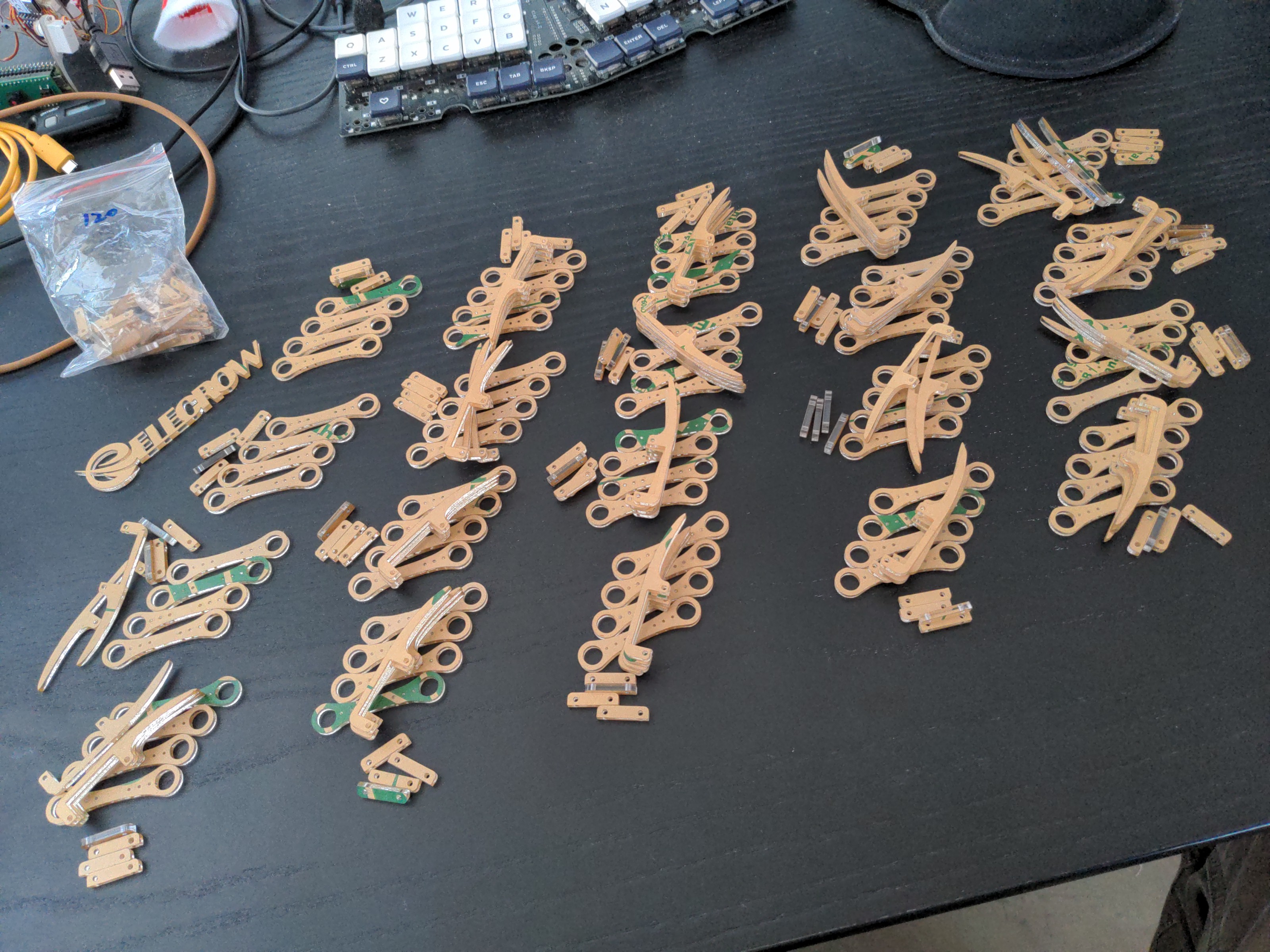
As you saw in the previous log, I'm working on clear assembly instructions, but we also need to prepare the kits. Almost all parts have already arrived, but I'm still waiting for the servos – that is going to be a big box.
![]()
![]()
-
Assembly Instructions
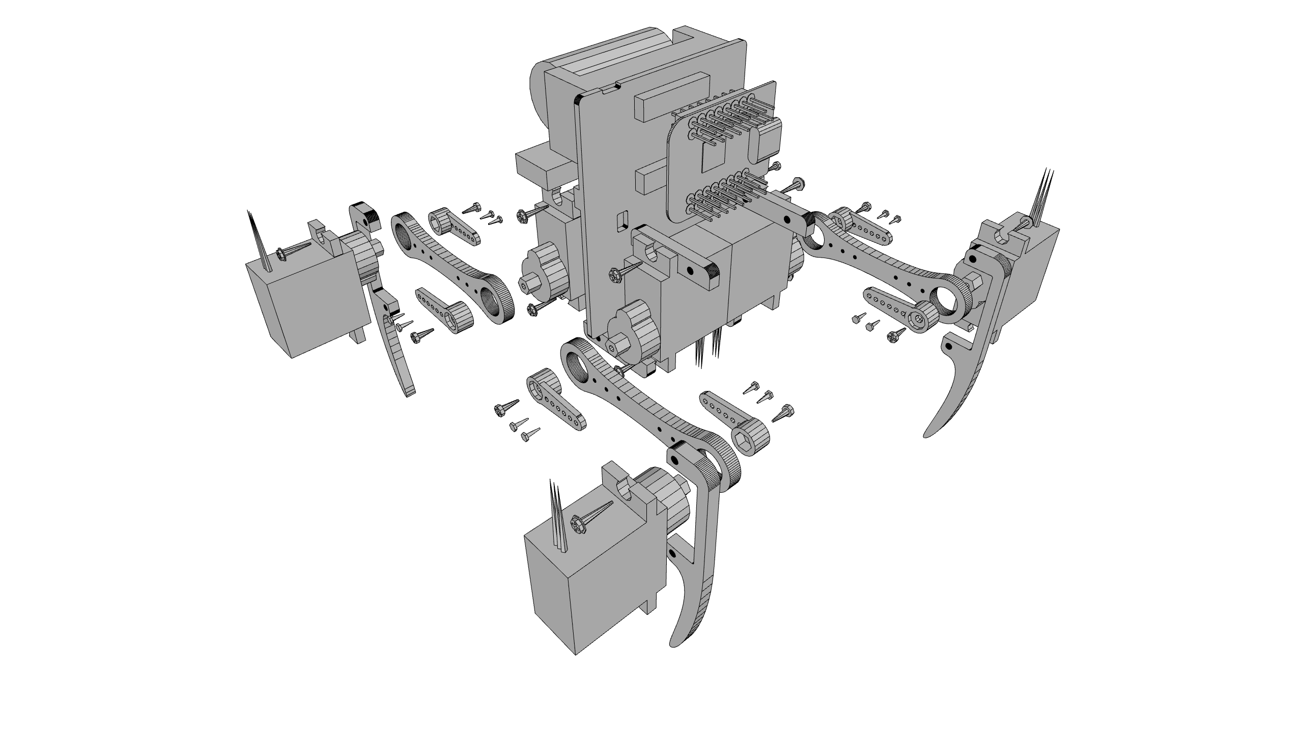
01/30/2023 at 22:28 • 0 commentsWith a workshop quickly approaching, it's time to spend some effort on the documentation. This time I want to make some IKEA-like step-by-step instructions, so I had to figure out a process for generating the images of the robot parts. Of course I already have an OpenSCAD model of the robot, I just had to update it a little and add some detail:
![]()
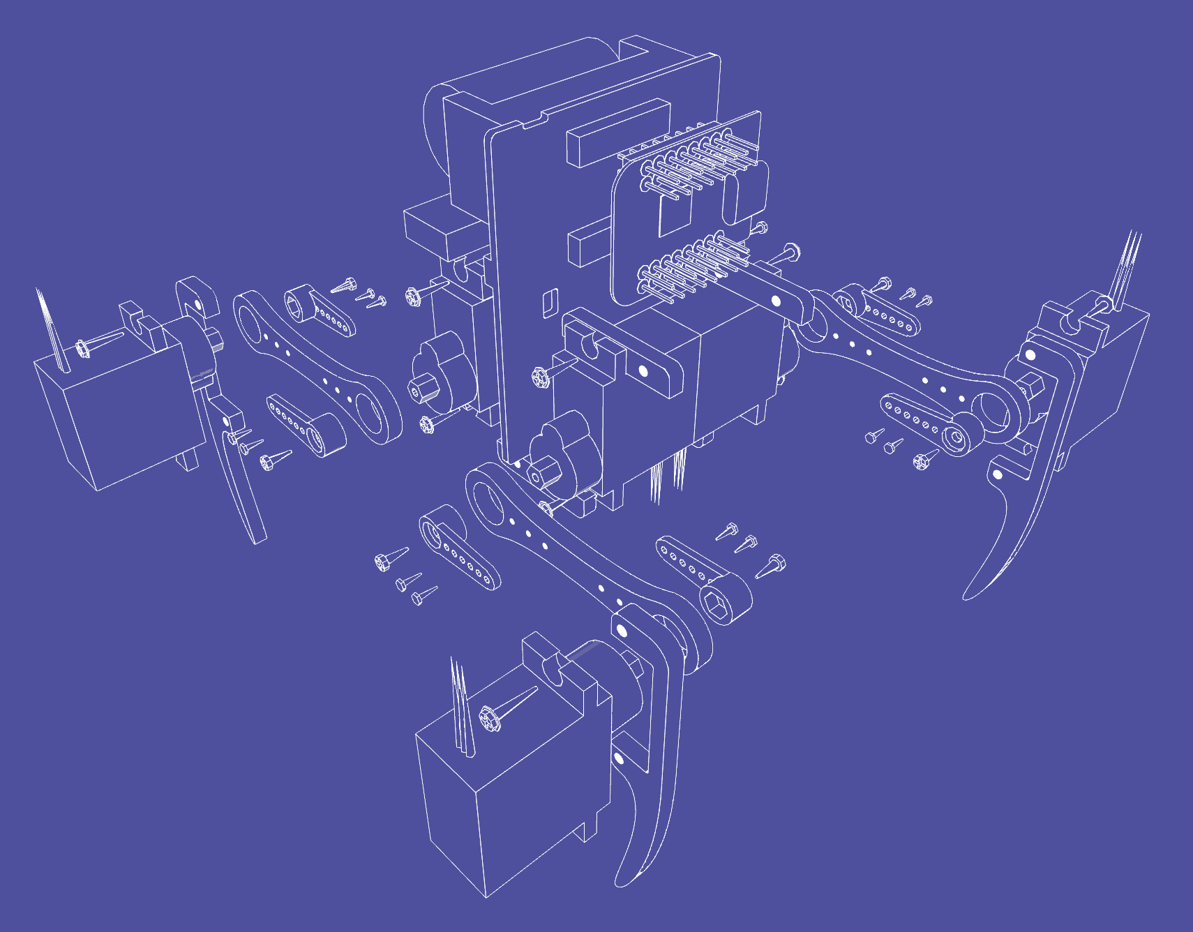
I parametrized the part positions, so that I can easily "explode" the whole thing, showing individual components. But this kind of image is too busy and looks bad when printed on paper in monochrome, so the next step is turning it into a wireframe. After some searching, I found an STL viewer that can do that, so I generated an STL of the robot from OpenSCAD and fed it to the viewer. I got something like this:
![]()
This is much closer to what I want, but there is still a lot of unnecessary detail cluttering the picture and making it hard to see clearly what comes where. So the next step is some manual cleanup in GIMP:
![]()
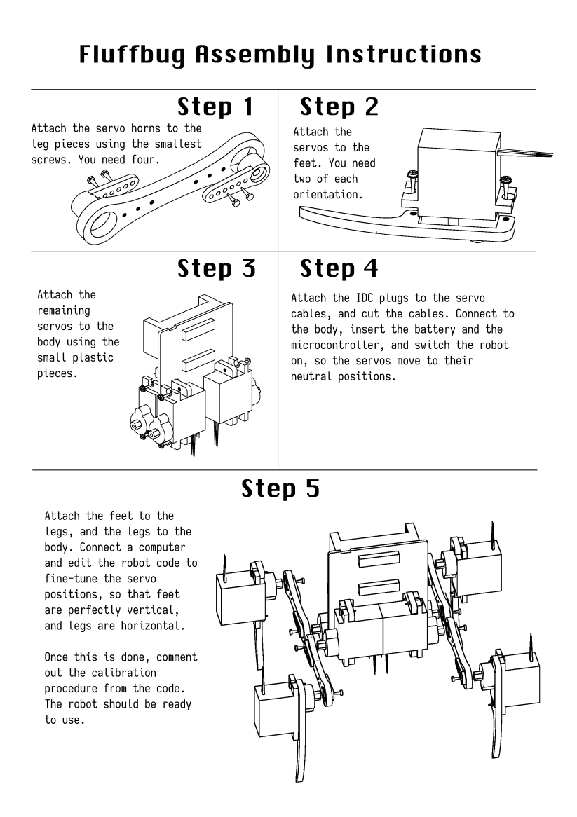
This is exactly what I wanted. Next, I quickly generated scad files for the individual steps of the assembly, and repeated the process to get the illustrations. An (almost) finished guide looks like this:
![]()
I still need to make the image for step 4, but I'm not sure I want to use OpenSCAD or something else for it. It has to show the orientation and order of the servo cables in the IDC plugs.
In the meantime, I also updated the git repository to include version 8.2 of the PCB and the new leg design.
-
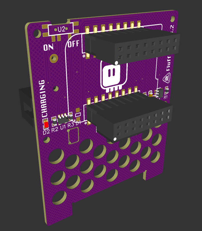
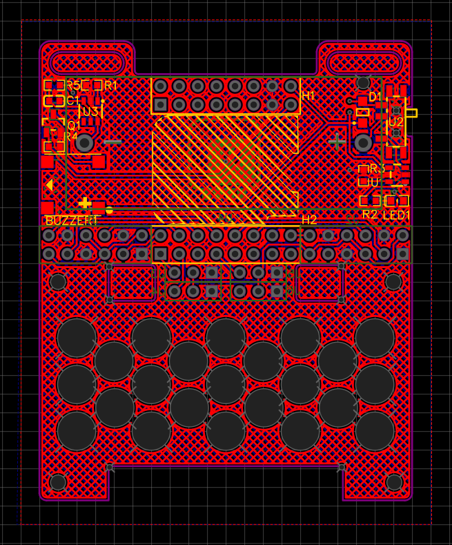
Version 8.2 of the PCB
01/19/2023 at 17:32 • 0 commentsAlong with migrating to all-SMD components (except for the battery holder), I also migrated with my PCB designs from Fritzing to EasyEDA. It's not as conductive to experimenting and just playing with things, but at least it's not openly hostile to it like KiCad is, and comes with a huge library of footprints.
Because of that, the latest version of the PCB is published at https://u.easyeda.com/account/user/projects/index/detail?project=ec4ce18f172848fc80a110ab474689c6 together with the schematic and the BOM. However, be careful about the female pin headers, you probably want to get some low-profile ones instead of those used in the footprint.
![]()
-
Can We Make It Simpler?
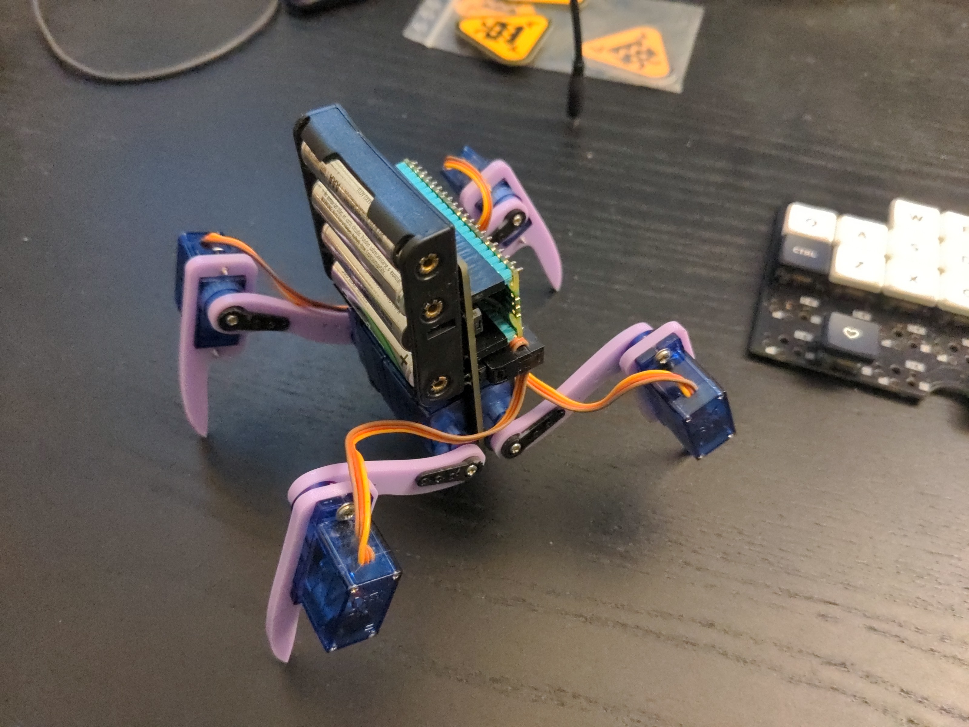
11/18/2022 at 19:09 • 0 commentsI'm pretty much happy with the physical design of this robot by now, but I also like to tinker, so I asked myself if it could be simplified any further? I noticed that 90% of the components on the PCB are dedicated to keeping the LiPO battery happy – the protection circuit and the charging circuit. What if we could use some other type of battery that doesn't require as much babysitting? Alkaline batteries are out, since one that could provide enough current for the servos would be way too heavy, but what about NiMH batteries? They can deliver higher currents than the alkalines, right?
Since I was ordering some PCBs anyways, I quickly made a modified version of the fluffbug PCB that comes with a 3xAAA battery holder on the back, and without all the protection and charging circuits – external chargers for NiMH batteries are common enough. I also took that opportunity to replace the S2 Mini footprint with a Raspberry Pi Pico footprint – just to see how that would work, especially since there is a version with WiFi now. I also ordered the batteries, and when everything came, I started testing.
![]()
It quickly became obvious, that three AAA NiMH batteries are enough to drive a single 9g servo, but not 8 such servos all at once. Even with a beefy capacitor to smooth the spikes in current, there simply was not enough power. So I replaced the battery holder with a 4xAAA one, and tried again. This works, but the robot is now considerably heavier than before, and can't move as fast. I consider the experiment to be failed, we are better off with the LiPO and all the extra components.
As a side experiment, since the pi pico doesn't have the limit to only 8 PWM outputs, as the esp32-s2 does, I also got to test the speaker with the fet on an actual WAV file with audiopwmio. I don't know if it's the low-pass filter that I added, or the transistor itself, but the results are disappointing – the audio is barely audible. If I keep the speaker in the future, I will probably use a proper amplifier with it.
I am still tempted to make a version of the PCB with the LiPO and the pi pico, but to be honest I'm not sure it would actually bring anything new right now. I might do it to try the SMD versions of the headers and the IDC sockets that I found, and that speaker amplifier, but really I should be focusing on programming, so that the robot actually does something more than just walking forward.
-
Asynchronous Face
10/13/2022 at 19:13 • 3 commentsI had some spare energy after work, so I sat down and implemented that asyncio-based display handling I mentioned previously. It seems to be working pretty well.
![]()
I still need to refactor the walking code, to make some parts of it part of the robot's library, and the rest a separate gait class. Slowly but surely it's getting there.
-
OpenSCAD
10/03/2022 at 22:21 • 0 commentsWith the robot mechanically pretty much good enough, the next steps are of course programming and documenting. The latter will require some drawings, so I sat down with OpenSCAD to make a simplified model of the robot, so that I can use it for assembly instructions. Here's a simple animation of the "exploded" view:
![]()
-
EasyEDA
10/02/2022 at 14:18 • 0 commentsBecause some people seem to have some kind of grudge against Fritzing, I decided to re-do the PCB for Fluffbug in EasyEDA, so that it can be easily ordered from JLC. They don't have all the parts (in particular, all 1kΩ resistors seem to be out of stock for some reason), but you can probably get those from somewhere else.
The project link is here: https://oshwlab.com/deshipu/fluffbug
![]()
-
asyncio
10/01/2022 at 18:01 • 0 commentsI finally had some time for coding today, first time in a long time, so I decided to rewrite the current gait code using asyncio.
![]()
The gait is still pretty much the same (I fine-tuned it a bit and sped up), and the code still has all those explicit waits everywhere, for the servo to get into position before doing anything else. I want to eventually have a function that would estimate how long it will take the servo to move, and do the waiting automatically for me. It could also do tweening, for more interesting movement profiles. But even with the current explicit waits asyncio is an improvement, because I can now easily add handling the display and/or sensors while walking.
The code follows:
---------- more ----------import robot import asyncio import time HEIGHT = 25 NEXT_LEG = (2, 3, 1, 0) TICK = 0.08 LEG_TILT = (1, -1, 1, -1) def calibrate(): for leg in robot.LEGS: leg.move() time.sleep(0.5) while True: time.sleep(1) async def init(): for leg in robot.LEGS: leg.move(y=HEIGHT) await asyncio.sleep(TICK) async def slide(): while True: for leg in on_ground: try: leg.move(dx=4) except ValueError: pass await asyncio.sleep(TICK) async def do_tilt(tilt): tilt = tilt * 5 robot.LEGS[0].move(y=HEIGHT) robot.LEGS[1].move(y=HEIGHT) robot.LEGS[2].move(y=HEIGHT) robot.LEGS[3].move(y=HEIGHT) await asyncio.sleep(TICK) robot.LEGS[0].move(y=HEIGHT + tilt) robot.LEGS[1].move(y=HEIGHT - tilt) robot.LEGS[2].move(y=HEIGHT + tilt) robot.LEGS[3].move(y=HEIGHT - tilt) await asyncio.sleep(TICK) async def do_step(leg): leg.move(dy=15) on_ground.discard(leg) await asyncio.sleep(TICK) leg.move(x=-30) await asyncio.sleep(TICK) await asyncio.sleep(TICK) leg.move(dy=-15) await asyncio.sleep(TICK) on_ground.add(leg) async def creep(): leg_number = 0 tilt = -LEG_TILT[leg_number] while True: leg_number = NEXT_LEG[leg_number] leg = robot.LEGS[leg_number] prev_tilt = tilt tilt = -LEG_TILT[leg_number] * 5 if tilt != prev_tilt: await do_tilt(tilt) await do_step(leg) async def main(): await init() creep_task = asyncio.create_task(creep()) slide_task = asyncio.create_task(slide()) await asyncio.gather(creep_task, slide_task) on_ground = set(robot.LEGS) asyncio.run(main())