deʃhipu
-
Version Six Assembled
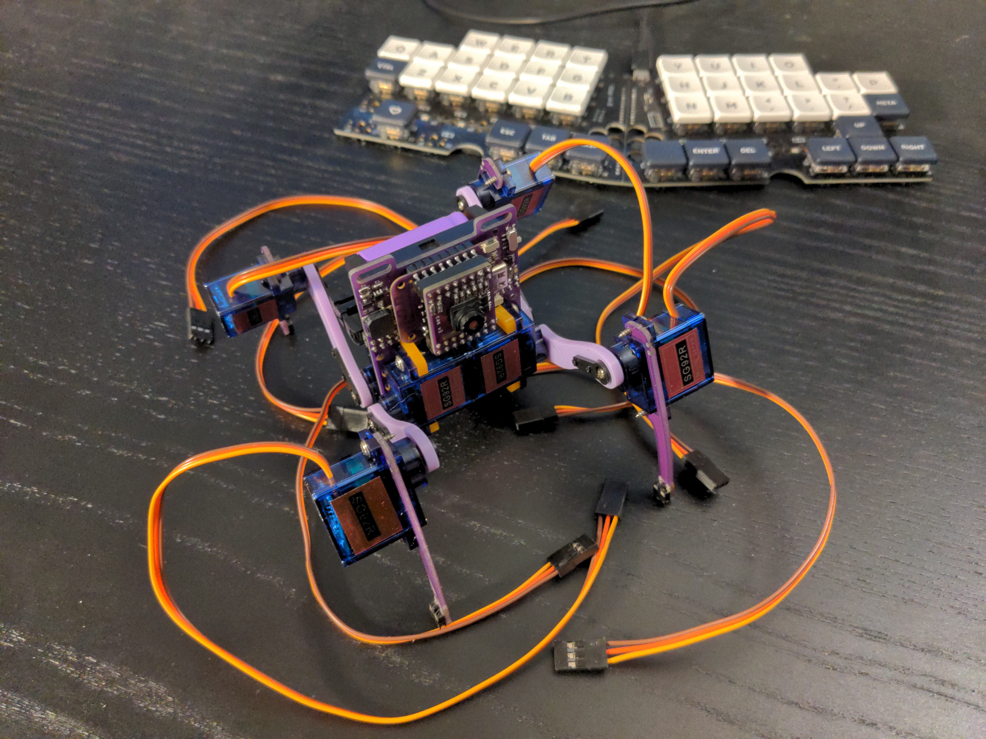
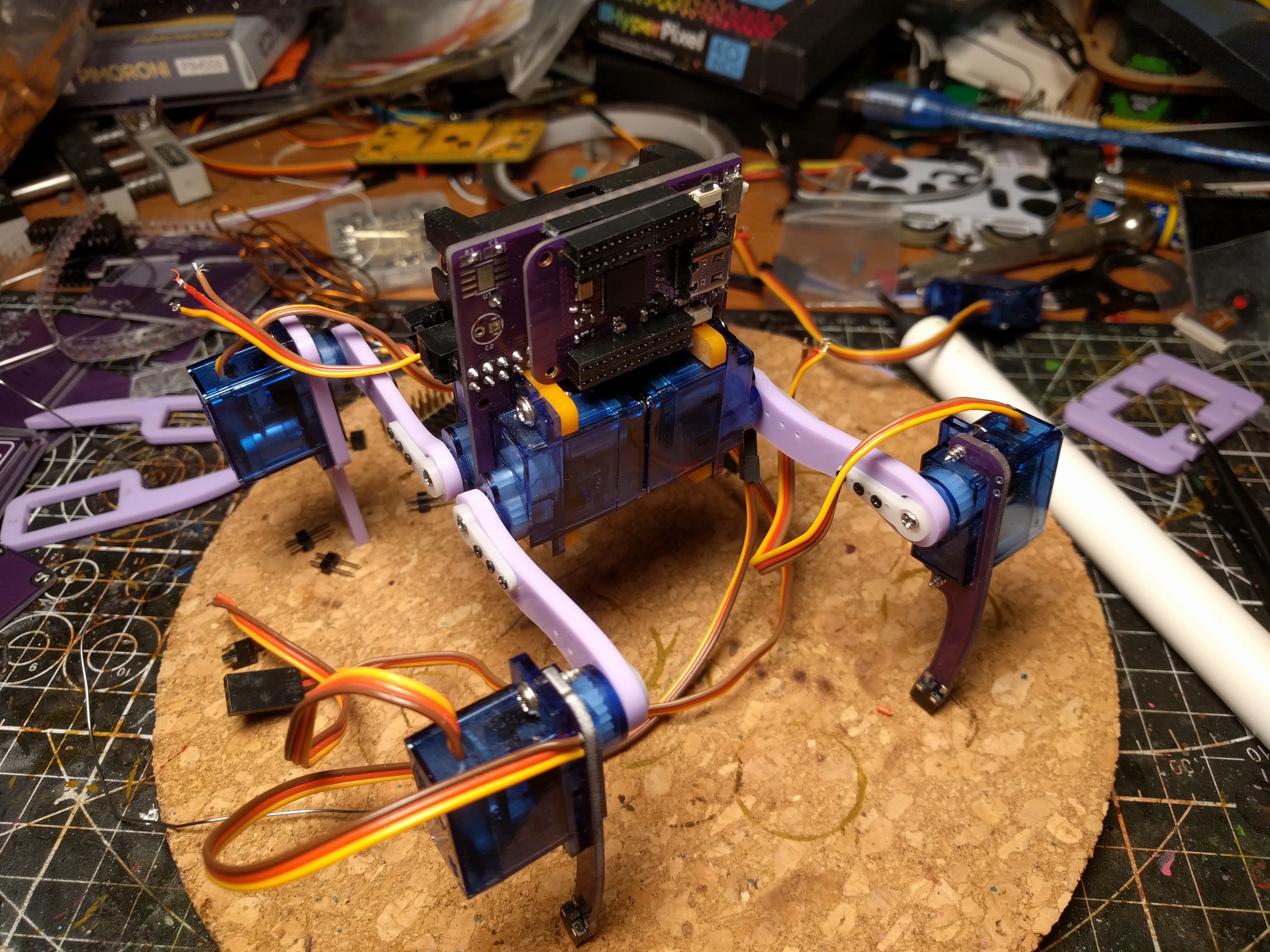
09/25/2022 at 11:48 • 0 commentsThe PCBs arrived, and I assembled everything. One thing that didn't work was plugging the S2 Mini into the staggered holes directly - you need headers for solid connection. Oh well. Another problem was the overcurrent protection of the new chip, that triggered whenever all the servos moved. Replacing one of the resistors with a bigger value one fixed this.
![]()
Sadly, I still didn't get the camera module working correctly, even with the new shield. Oh well.
![]()
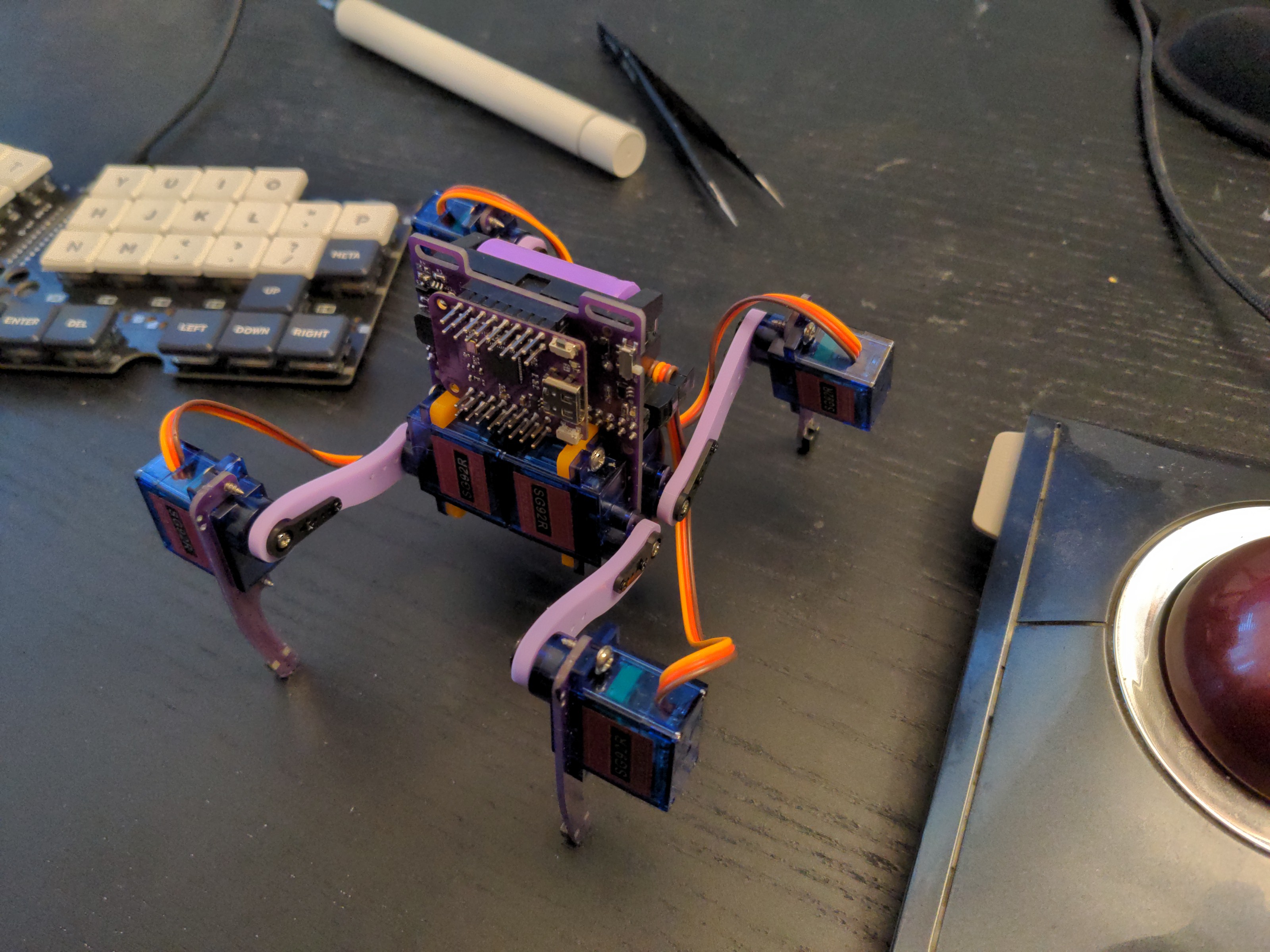
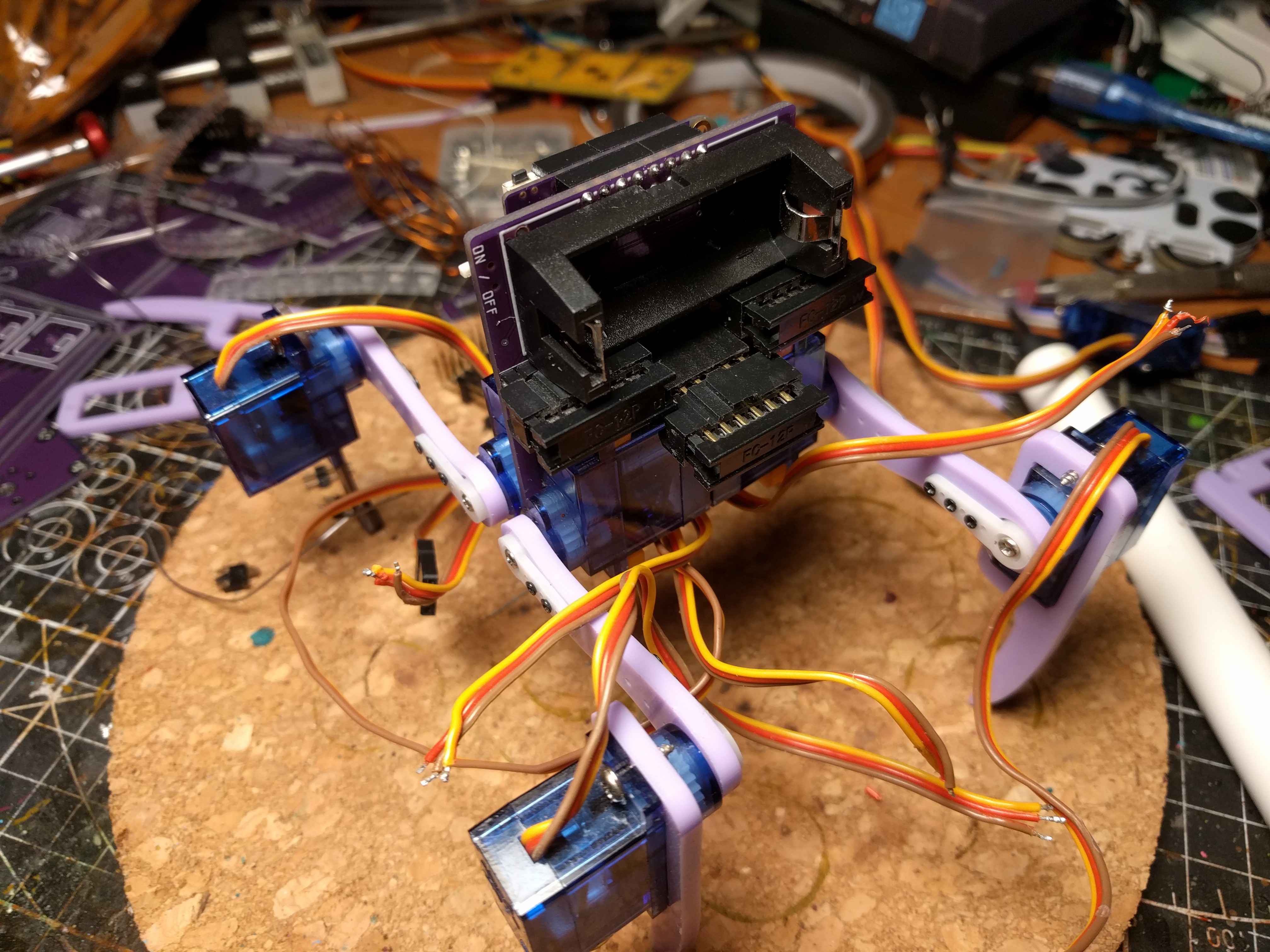
I used the PCB legs with switches, but I didn't connect them yet.
-
Version 6
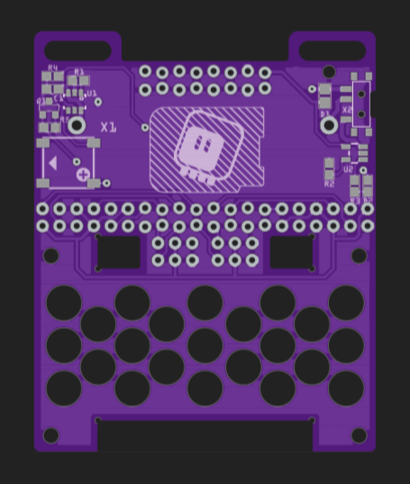
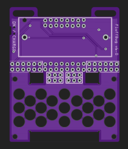
09/16/2022 at 16:19 • 0 commentsWhen I recently started looking for parts to make more of those robots, I had an unpleasant surprise: the battery protection chip that I used, HT3062E, can no longer be easily bought. That is a big problem, so I went to look for another chip instead. Unfortunately, there don't seem to be very many integrated solutions out there – most chips require separate mosfets, which is something I would rather like to avoid. So this time I went for the DW07D, which is for a bit lower current, but should still work. Unfortunately it comes in a different package and requires different connections, so a new PCB design is required.
![]()
![]()
I also added a mosfet for the speaker, and some handles at the top of the PCB, to make it easier to attach things to the robot.
-
Maker Faire
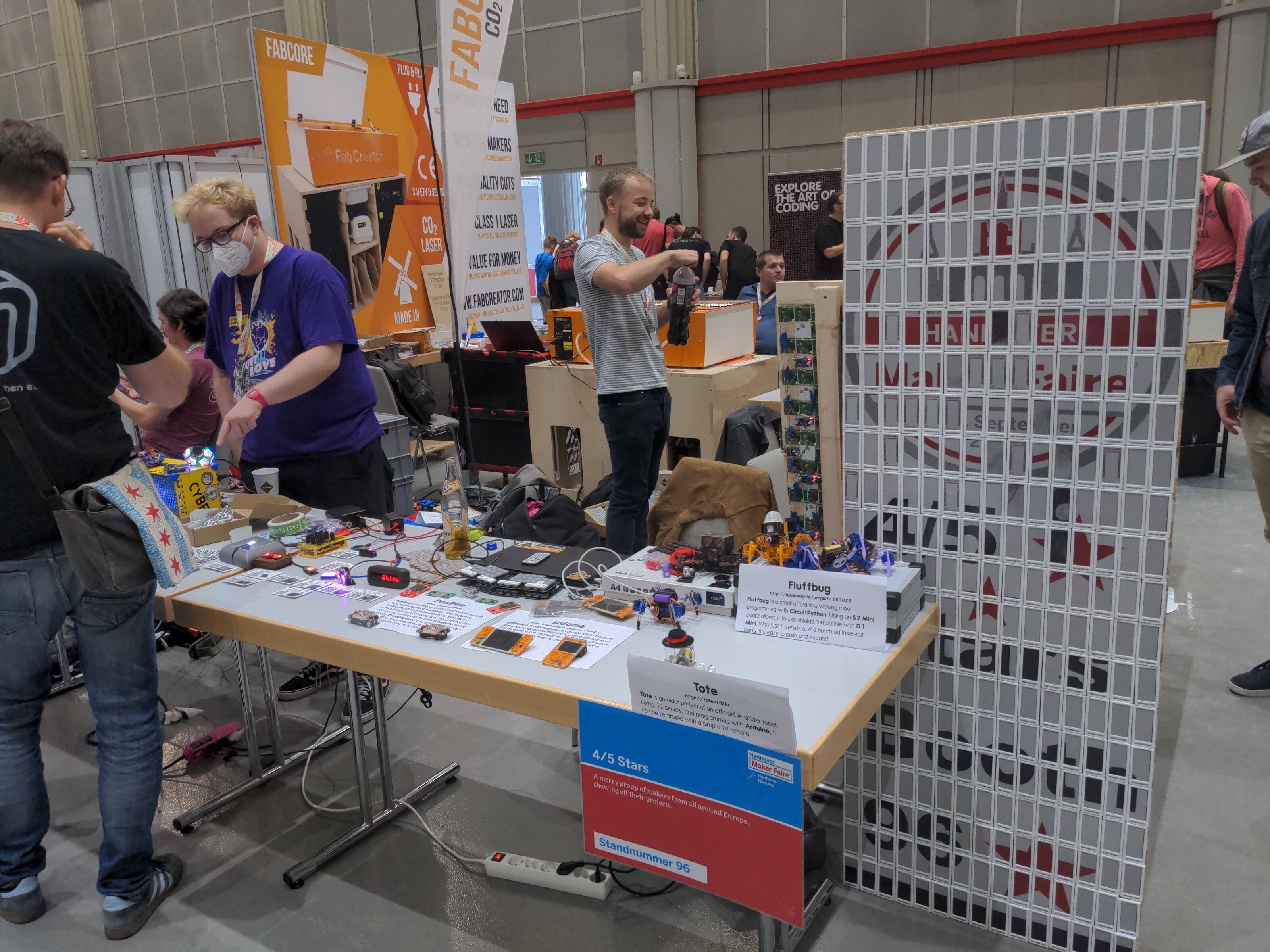
09/15/2022 at 09:14 • 0 commentsFluffbugs went to Hannover last weekend, together with some other bots, game consoles and a bunch of keyboards. We had a table labeled 4/5 Stars, and you could see all our stuff there.
![]()
Since Fluffbug still mostly just walks forward, most of the work was done by the two #Tote robots I also brought. But a lot of people stopped by to see them walking around.
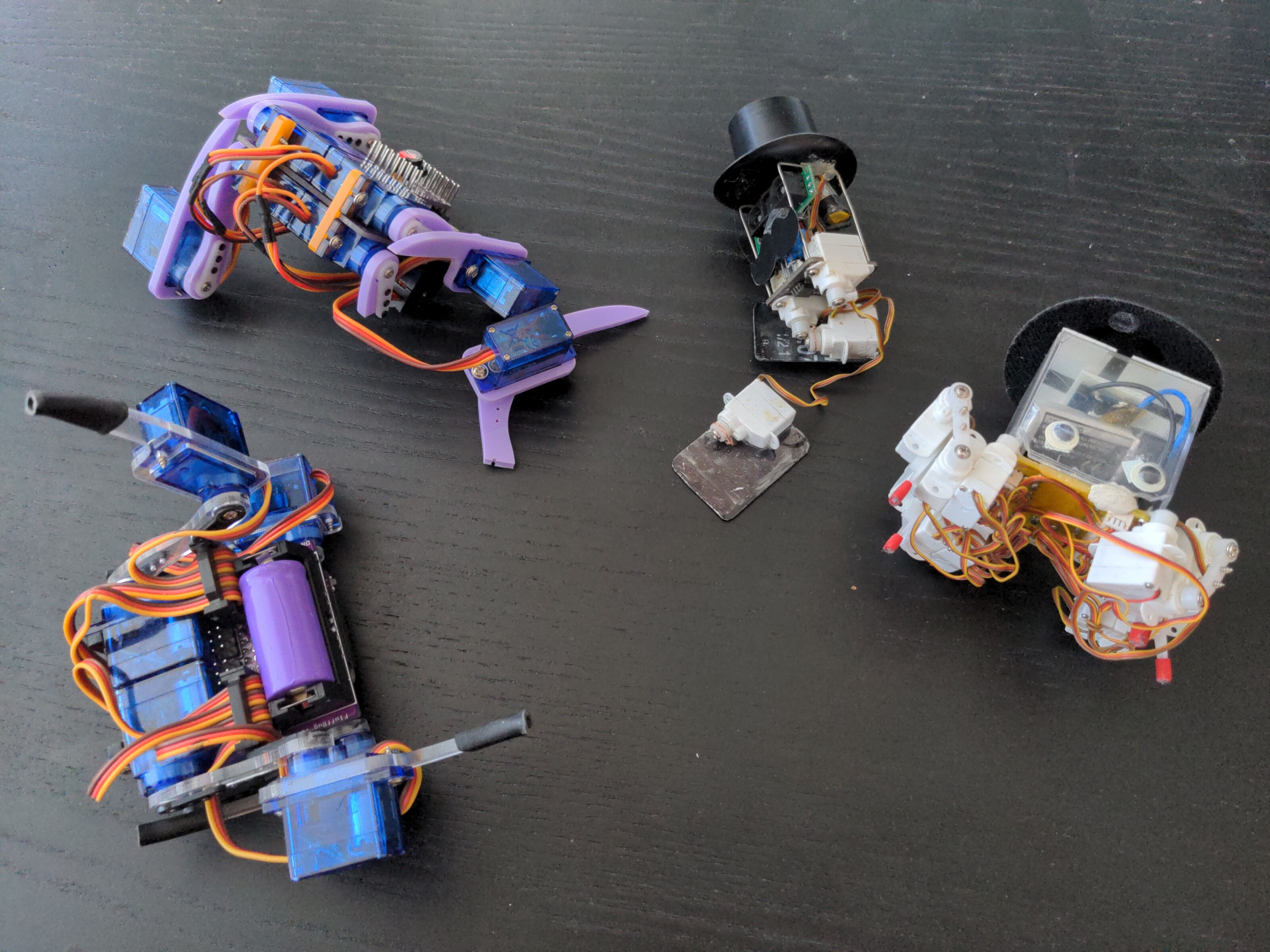
Afterwards, I had some fixing to do.
![]()
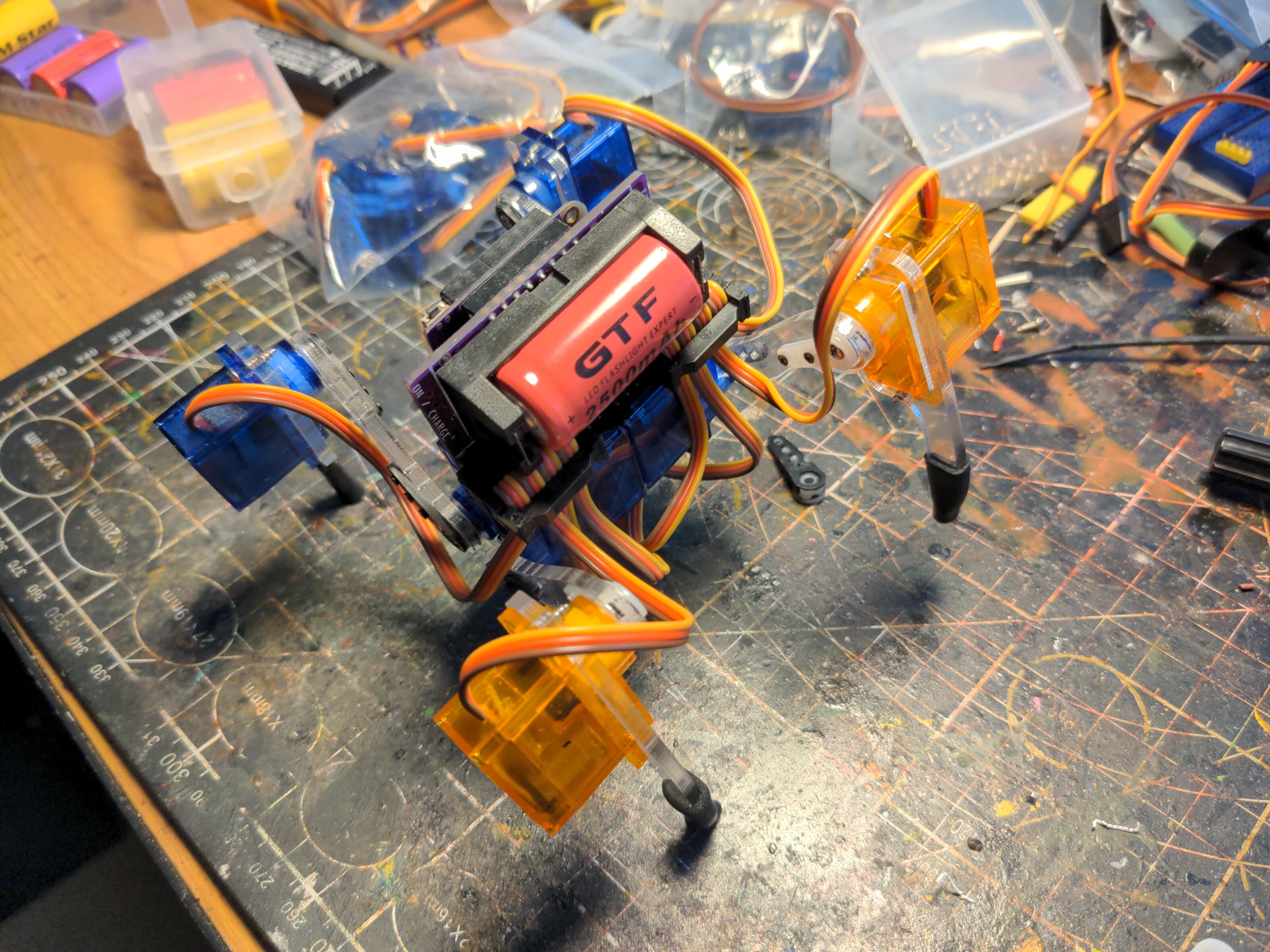
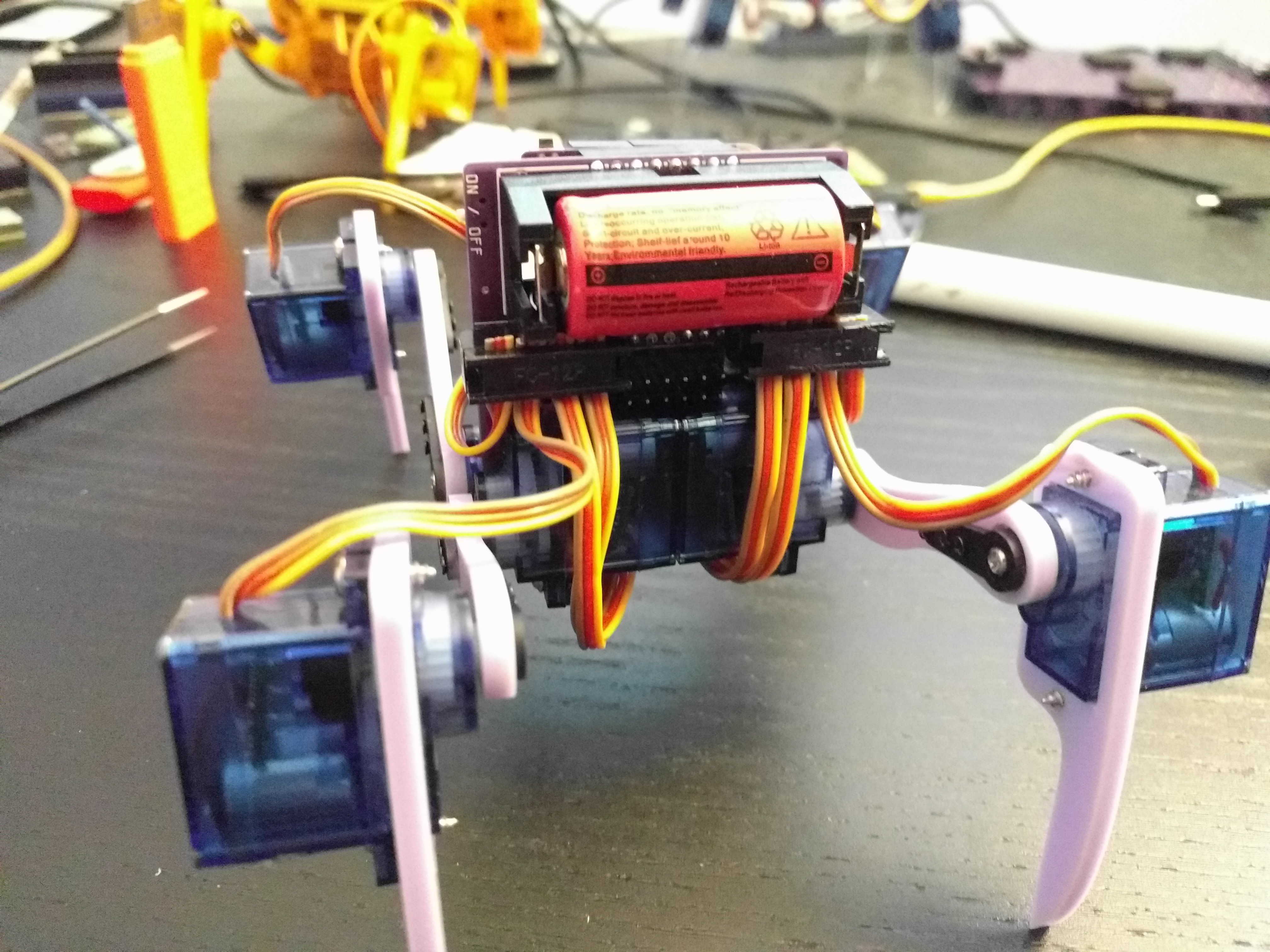
My main Fluffbug now has two new servos, which don't quite match the rest, but I think I like it.
![]()
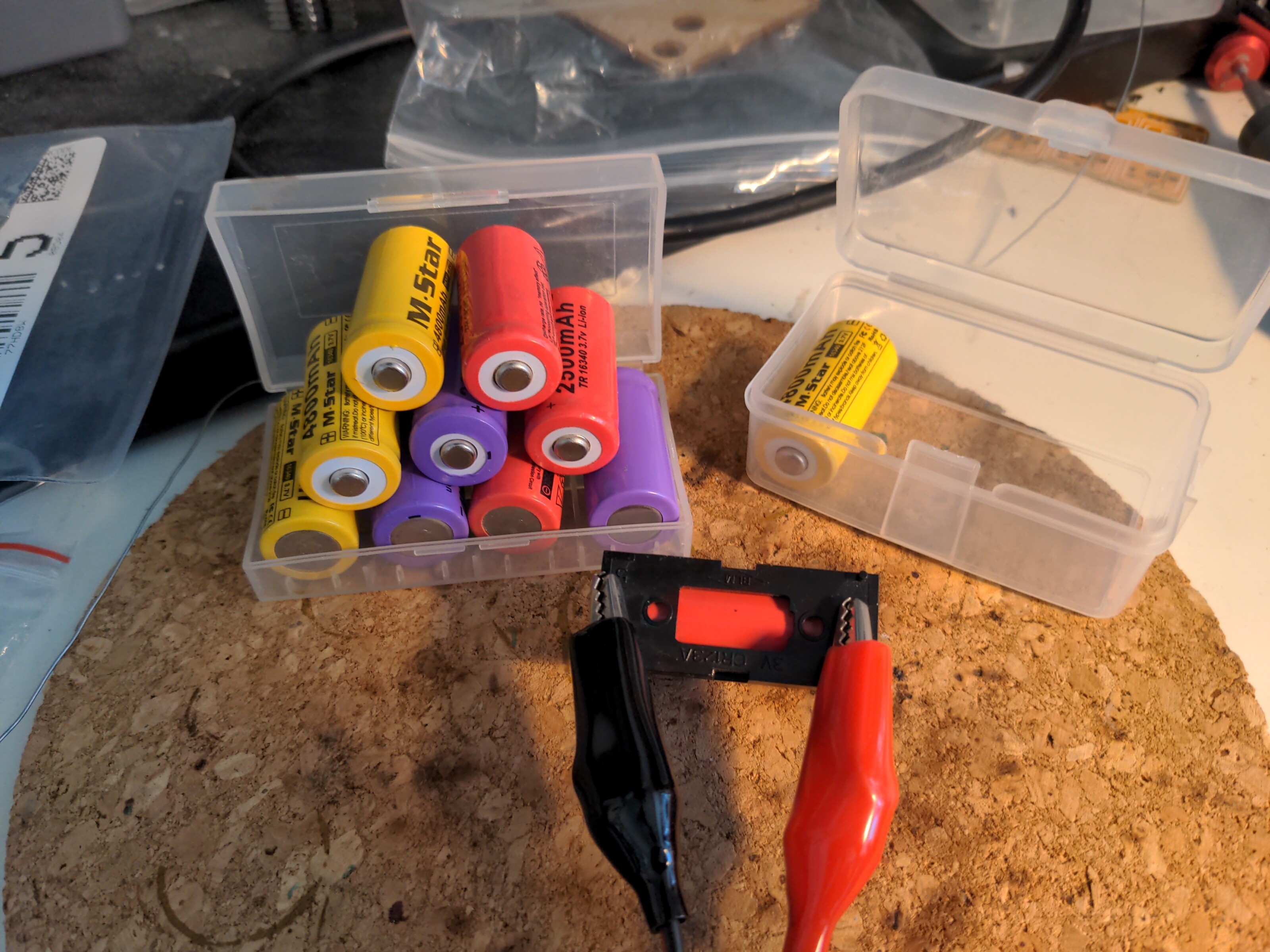
I also recharged all the batteries.
![]()
-
Put a Face to a Robot
07/29/2022 at 21:11 • 0 commentsEverything is better with eyes. Putting goggly eyes on things makes them instantly relatable and cute or creepy. We simply can't remain emotionally neutral to something that looks at us. So I decided that the robots need faces.
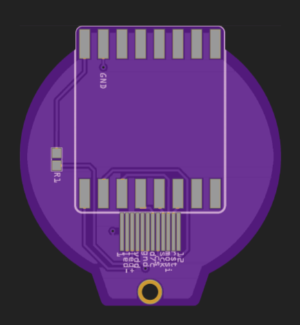
Of course I could have used one of the many Wemos D1 shields available on the market to add an OLED screen, a TFT screen or even just a LED matrix, but where is the fun in that? I recently got a new round screen to work, so I decided to make a shield for it, and to design it so it works well with those robots.
![]()
The back side has a lot of free space for a silkscreen, so what should I put behind a face? Of course!
![]()
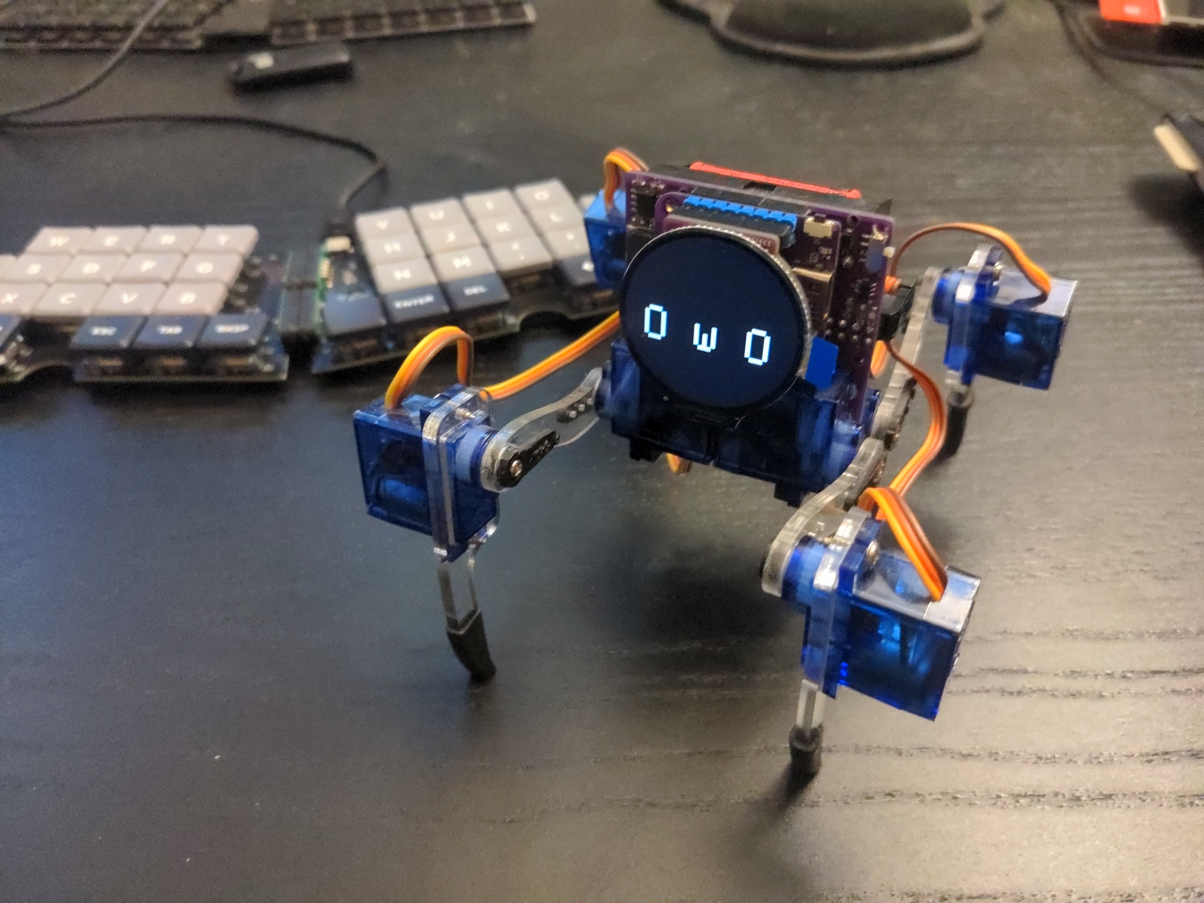
This way I can use the spare PCBs without a display to decorate other robots. That was a week ago, now the PCBs have arrived, so I got it all assembled and working:
![]()
My work here is done. Here is the code I used:
import board
import displayio
import busio


_INIT = (
    b"\xFE\x00"  # Inter Register Enable 1
    b"\xEF\x00"  # Inter Register Enable 2
    b"\xB6\x02\x00\x00"  # DFC S1>S360 source G1>G32 gate
    b'\x36\x01\x48'  # MADCTL
    b'\x3a\x01\x05'  # COLMOD
    b"\xC3\x01\x13"  # PWRCTL2 VREG1A=5.06 VREG1B=0.68
    b"\xC4\x01\x13"  # PWRCTL3 VREG2A=-3.7 VREG2B=0.68
    b"\xC9\x01\x22"  # PWRCTL4
    b"\x66\x0a\x3c\x00\xcd\x67\x45\x45\x10\x00\x00\x00"
    b"\x67\x0a\x00\x3c\x00\x00\x00\x01\x54\x10\x32\x98"
    b"\x74\x07\x10\x85\x80\x00\x00\x4e\x00"
    b"\x98\x02\x3e\x07"
    b'\x21\x00'  # INVON
    b'\x11\x80\x78'  # SLEEPOUT
    b'\x29\x80\x14'  # DISPLAYON
)
displayio.release_displays()
spi = busio.SPI(clock=board.IO7, MOSI=board.IO11)
bus = displayio.FourWire(spi, chip_select=board.IO12, baudrate=40_000_000,
        reset=board.IO5, command=board.IO9)
display = displayio.Display(bus, _INIT, width=240, height=240)
display.root_group.scale = 6
display.root_group[1].x = 0
display.root_group[1].y = 0
print("\x1b[2J")
print(" O w O")
I might come up with something more complex later...
-
Better Gait
07/19/2022 at 14:39 • 0 commentsI took the robot with me to the EuroPython 2022 conference, hoping that I will have some time during the maker hacking sessions or during the sprints to work on the code further. And I did manage to improve the gait considerably:
There is of course still a lot of room for improvement. I need to rewrite the code to make it more modular and maybe make use of the async features of CircuitPython. I also need to think about how to move the servos more fluently, possibly along defined motion profiles, to give the robot a more organic look (and put less strain on the servos too).
Then, I will work on a remote control program for the #PewPew S2 console, to control the robot over WiFi or ESPNow.
-
First Steps
03/13/2022 at 17:16 • 0 commentsToday I decided to make this robot walk, however awkward a walk it will be. I didn't write the code for smooth movement of the servos, so it's all jerky and crude, but it is something.
The most important change now is to make the tiling of the body smoother. Right now it's really unacceptably sudden, and since it moves the whole robot, it puts a lot of strain on the servos. Next will come fine-tuning of the step size and movement speed. Once I have it all reasonably smooth, I will experiment with turning.
-
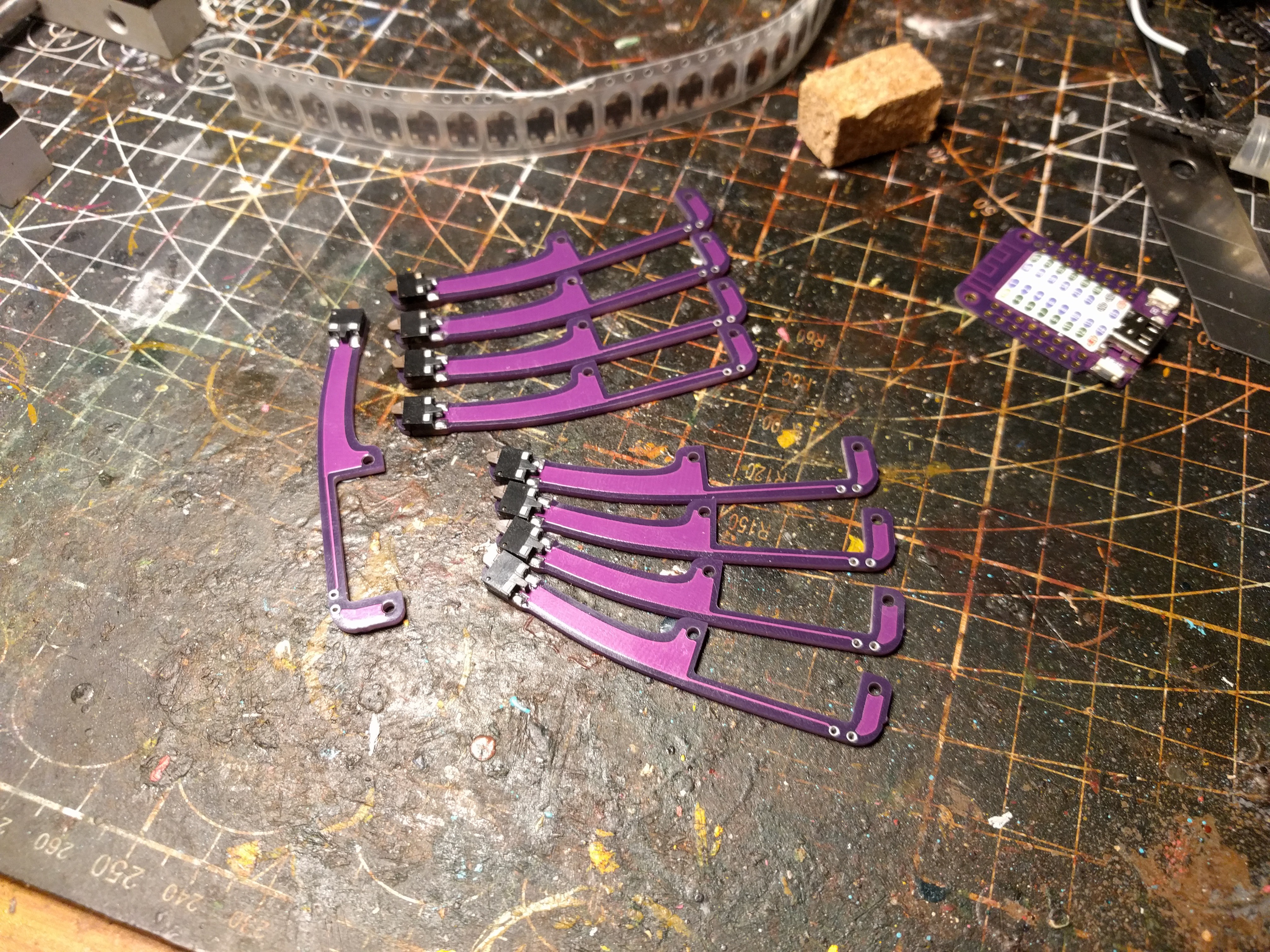
Legs
01/13/2022 at 12:57 • 0 commentsNot much is happening, I'm still not working on the gait, but in the mean time the switches for the legs arrived, so I assembled a few:
![]()
I'm also at version 5 of the PCB now, with all the spacing problems mentioned previously fixed, and a piezo speaker added back. Seems the problem with the ribbon cable connectors can be solved by inserting the cables from the top instead of the bottom of the plug.
-
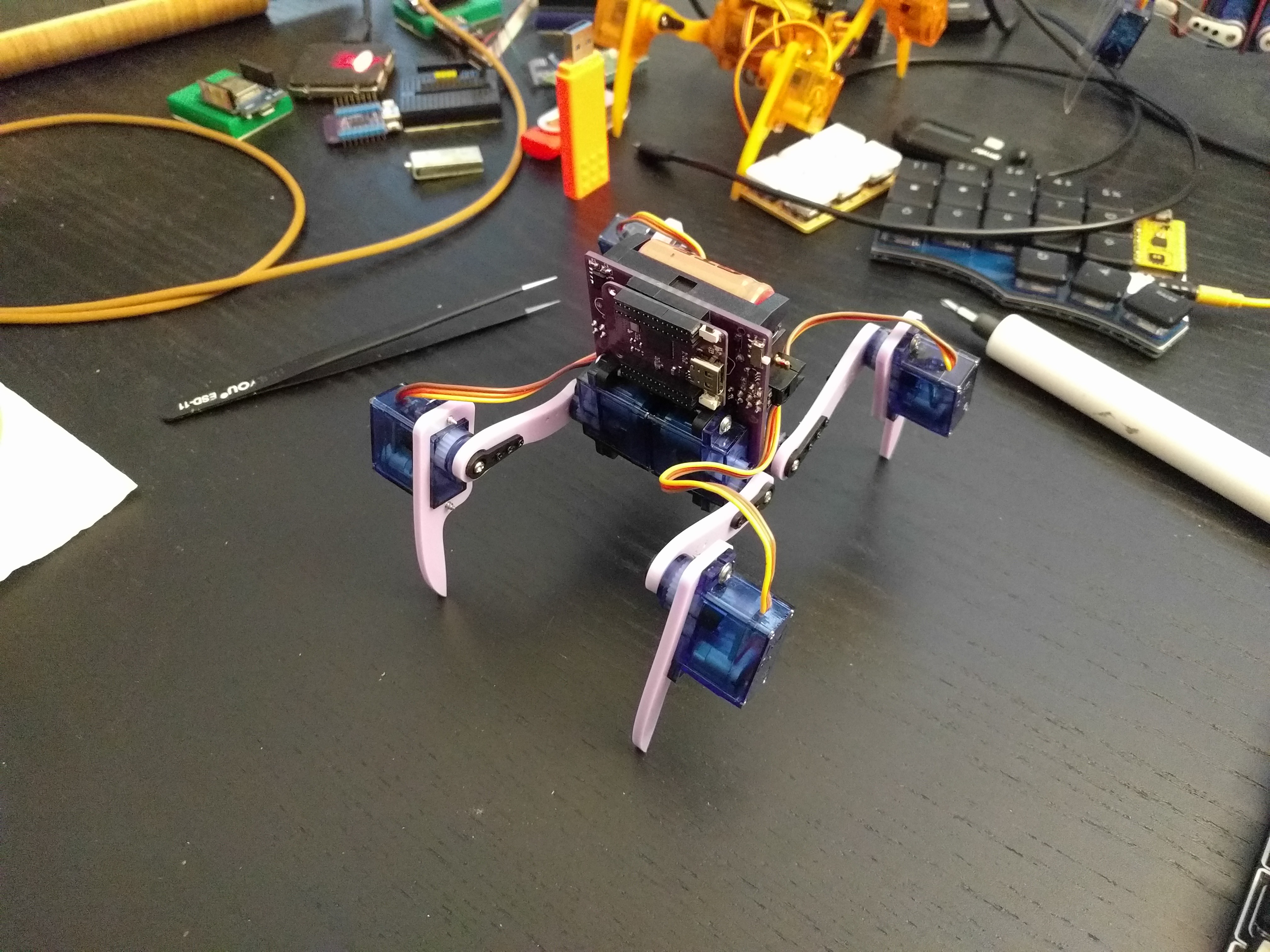
Assembled and Programmed
11/07/2021 at 17:31 • 0 commentsOver the weekend I finally had time to finish assembling the robot, and to program the S2 Mini for it. No, I still didn't implement a gait — just the IK code I had before.
![]()
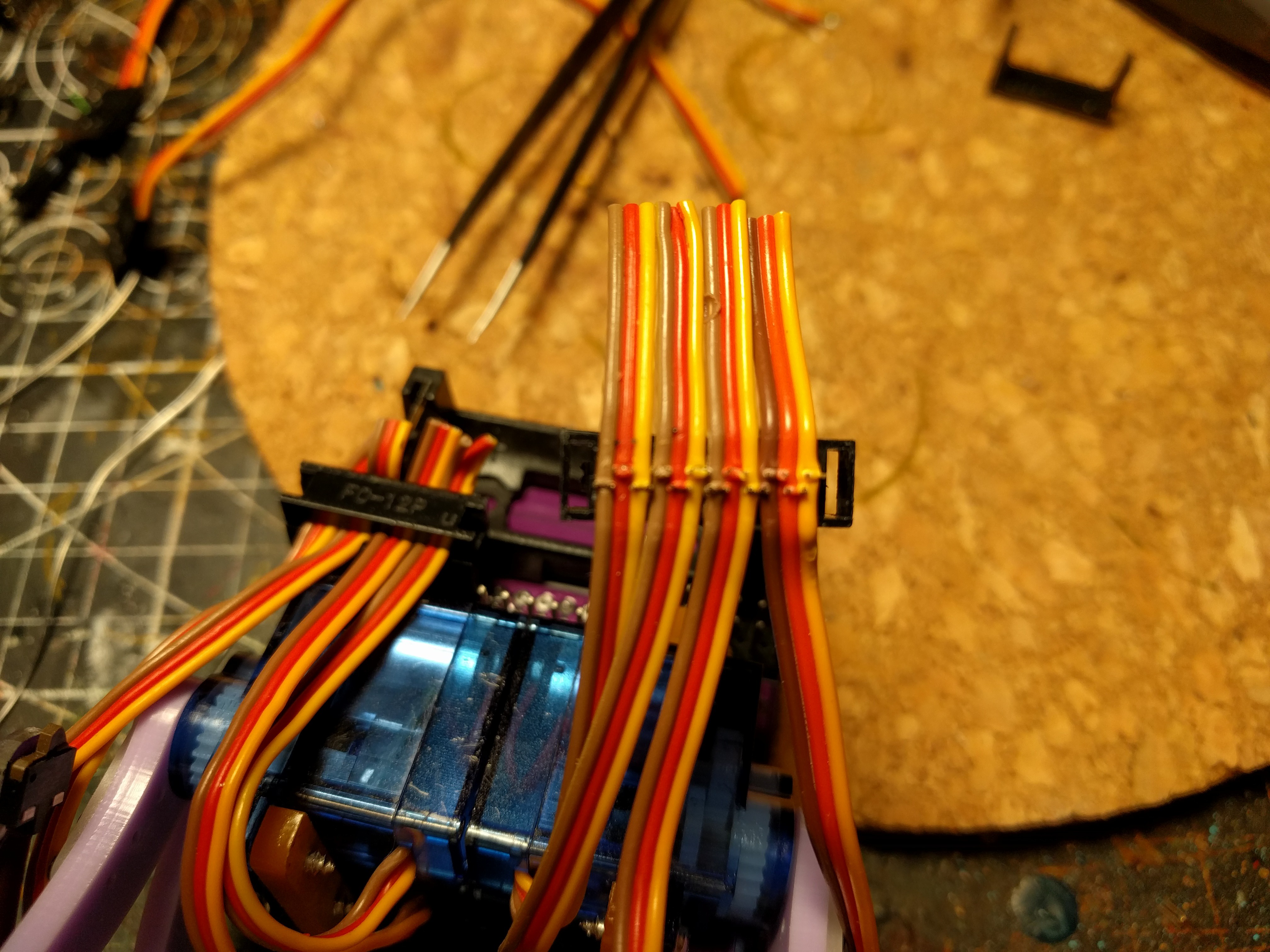
Surprisingly, there were no problems with the PCB — other than the lack of room between the battery and the servo sockets that I mentioned previously. I even got to test the battery protection circuit, because unfortunately those servo sockets make it very easy to short-circuit the cables:
![]()
See, the right-most servo cable, that got a bit skewed, and the contacts shorted all the wires together.
Extra care needs to be taken to align the cables straight when doing this.
![]()
-
PCB Physical Fit
11/02/2021 at 18:31 • 0 commentsI got the PCBs today, while I still need to solder up all the components and program it, I was already able to test how it comes together physically. In short, it's workable, but still needs some small adjustments.
![]()
The front side of the robot is pretty much fine. The S2 Mini fits in there and sits tight, the USB-C socket has enough clearance, the BOOT button is accessible, the RESET button is a bit hidden, but still accessible with a screwdriver or tweezers. The slots for attaching the servos are the right size and in the right positions.
The legs work, but I would like to move the switch a little bit further down, to give it more travel before the leg hits the ground. I might also make the wire holes a bit bigger, to allow using the servo plugs which will be cut off from the servos.
![]()
The back side needs work. I didn't take into account the thickness of the ribbon cable plugs, and the fact that they are keyed with a nub on top — so there is not enough clearance between them and the battery holder. At the same time, the battery holder is not flush with the top of the PCB, so there is actually room to move it. I had to use stacking pin headers to add distance for the middle plug, otherwise the side plugs and the servos don't leave enough room for it.
I also want to add some more holes, aligned with the holes in the S2 Mini and in the battery holder. I probably won't be putting bolts in them, but there is room, so why not have them.
-
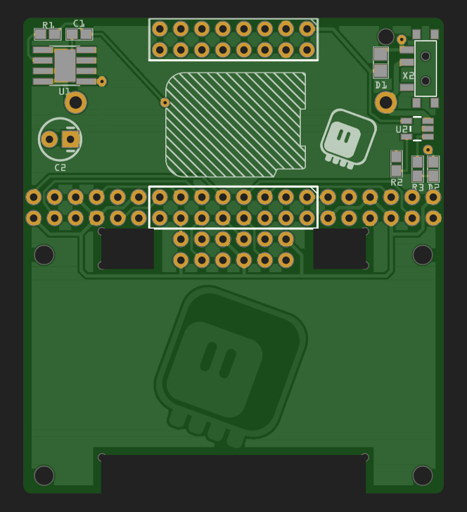
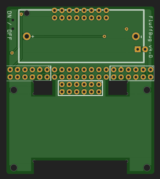
Version 4 of the PCB Routed
10/24/2021 at 11:44 • 0 commentsIt were busy few weeks, but now it's finally all over, and I had some time to finish the version 4 PCB. It turned out to be much simpler than anticipated — the difficult part was figuring out which pins I can use, and that I did already previously. So I ended up with a simple board like this:
![]()
![]()
I have to say that I forgot how much using a ready development board simplifies the design. It's basically just connecting things together, and a little bit of more complexity around the power.