One would think that the logical conclusion to this method is a hardware based approach. This log examines how it might work and what limitations apply.
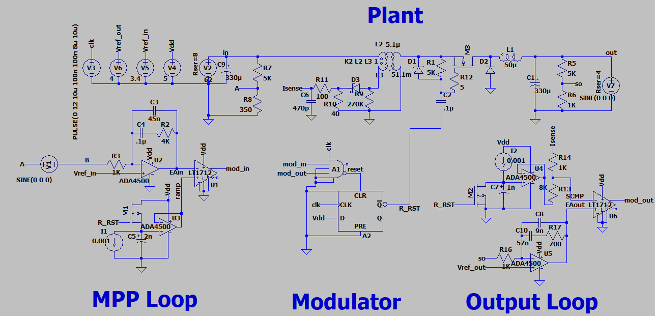
For simplicity, a buck converter with current mode control is used to model the MPP loop in LTspice. The current mode output control loop uses a linear ramp for slope compensation and a type-2 error amp to control output voltage. The comparator's output is gated to a flip-flop that drives the modulator and terminates the duty cycle.
The MPP loop uses voltage mode control, also with a type-2 error amp. A linear ramp, calibrated to the maximum duty cycle of the modulator, provides timing for a comparator to terminate the duty cycle.
The model includes voltage sources that can be modified to inject signals or transients to test stability and plot gain & phase margin. To measure gain & phase margin, comment out the '.tran' statement and set the 'parm t0...', '.tran', '.step', and '.measure' statements active. The frequencies to measure, and type of measurement, can be changed with the '.step parm Freq' statement. The sine voltage across nodes A & B must be set to 10mV and the variable {Freq} set in the 'Freq' field. Warning: the simulation can take hours, particularly at low frequencies. I believe that the linear ramps contribute to much of this.
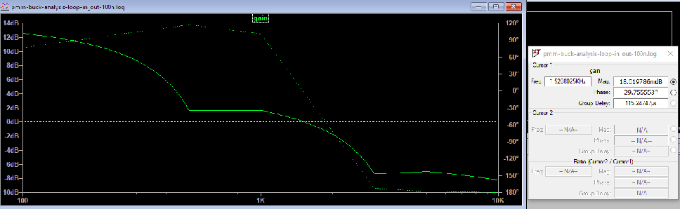
This gain & phase plot of the MPP loop shows a phase margin of just 29 degrees at a cut-off frequency of about 1.5kHz. Moving it down to 1.2kHz would likely get the phase margin up to a much safer 45 degrees. More could be done to increase phase margin and increase the cross-over frequency, such as resorting to a type-3 configuration. The input filter configuration for a given design will have significant influence on the bandwidth available for the MPP loop. For this simple buck with only bulk capacitance (no ESR is modeled) a single pole exists, so along with the error amp the maximum phase margin available is 90 degrees.
For the tightest MPP tracking the loop should be slightly faster than the output loop, but with such a low cut-off frequency this isn't possible. Minimally, the MPP loop should be faster than load induced ripple, such as that caused by an inverter (120Hz).
1.2kHz isn't fast for a SMPS control loop, but for MPP tracking it is likely fast enough to compensate for load induced ripple as well as environmental factors (e.g. shading, cloudy days, etc.). So, might it be better to stick with firmware? After all, it is easier to tailor the gain curve and add compensation for load, PV temperature, etc.
The answer is that it depends on how well MPP must be tracked. Matching a 1.2kHz hardware loop requires sampling at least every few degrees. Sampling every four degrees is 9.25uS or 110KSPS. The sample set must be integrated and anti-aliased; either substantial computational overhead for the MCU or handled by a DSP. Hence, demanding applications that choose a firmware approach will require a fast MCU (100MIPS) with DSP.
As previously shown, less capable processors can also use the firmware approach but must accept poor tracking in non-steady state conditions. Setting a MPP voltage range (as opposed to tracking a specific voltage) is a method for dealing with input voltage ripple induced by the converter design as well as load characteristics.
Discussions
Become a Hackaday.io Member
Create an account to leave a comment. Already have an account? Log In.