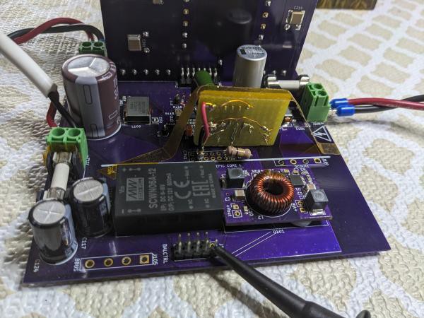
I finally got a chance to try the hardware MPP approach in a working converter. I used the prototype for my Solar Charger. I had to remove one of the SEPIC cores to make room and hack a few changes into the backplane.
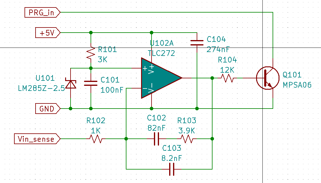
The MPP control loop is similar to the Closing the Loop (HW) log - a type 2 integrator with a zero at 500Hz and a pole at 5kHz. The phase boost is necessary because of a pole near resonance (~800Hz) between the input bulk capacitance and the SEPIC coupled inductor.
A challenge with any multi-phase converter is how to servo the output control loops equally & simoultaneously, and is very dependent on controller architecture. It turned out to be easy with the PIC. The output voltage control loop is common to all phases and drives the ramp generators (PRGs) for each phase' inner current loop. Rather than trying to directly limit duty cycle as I had earlier proposed, the MPP loop simply subtracts voltage from the error amp's output to obtain a duty cycle that maintains the input voltage at the MPP value.
A 1K resistor is placed between the error amp output and the PRG input pins and Q101's collector connects to the PRG side. R104 limits Q101's gain to the linear region. When the MPP loop engages, the PRG's input voltage is reduced which directly limits duty cycle. However, the output error amp knows no different - its gain & phase profile haven't changed. It sees the output voltage dropping and demands maximum duty cycle so, when the input voltage rises the converter's output power immediately increases.
A few hacks to the charger's backplane and firmware were required to test this.
Firmware- Disable output voltage sense.
- Remap PRG inputs from controller pin 22 to pin 3.
- Set input voltage measurement ratio to 20.
- Remove R112 & C129.
- Cut trace between R112 and via routing to bottom layer (output voltage sense must be kept intact to error amp).
- Install 1K resistor at R112.
- Add jumper from controller pin 22 to terminal 1 of R112 (30AWG magnet wire).
- Change R103 to 549 ohms (~2.5V for Vin=50.5).
- Add 100K resistor across pins 1 & 3 of J110 (to keep card over-temp from tripping).
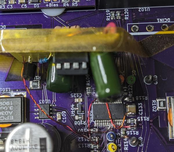
I built the MPP circuit on perf board using old parts I had lying around and used the power leads & polyimide tape to hold the board in place. Vin_sense connects to terminal 1 of R115, and PRG_in connects to terminal 2 of R112. Twisted pair (30AWG magnet wire) with a GND lead is used for both to maintain signal integrity.
I don't have a Vector Network or Frequency Response Analyzer so I did the next best thing: beat on it with a variety of simulated input & output impedance variations to observe response & stability.
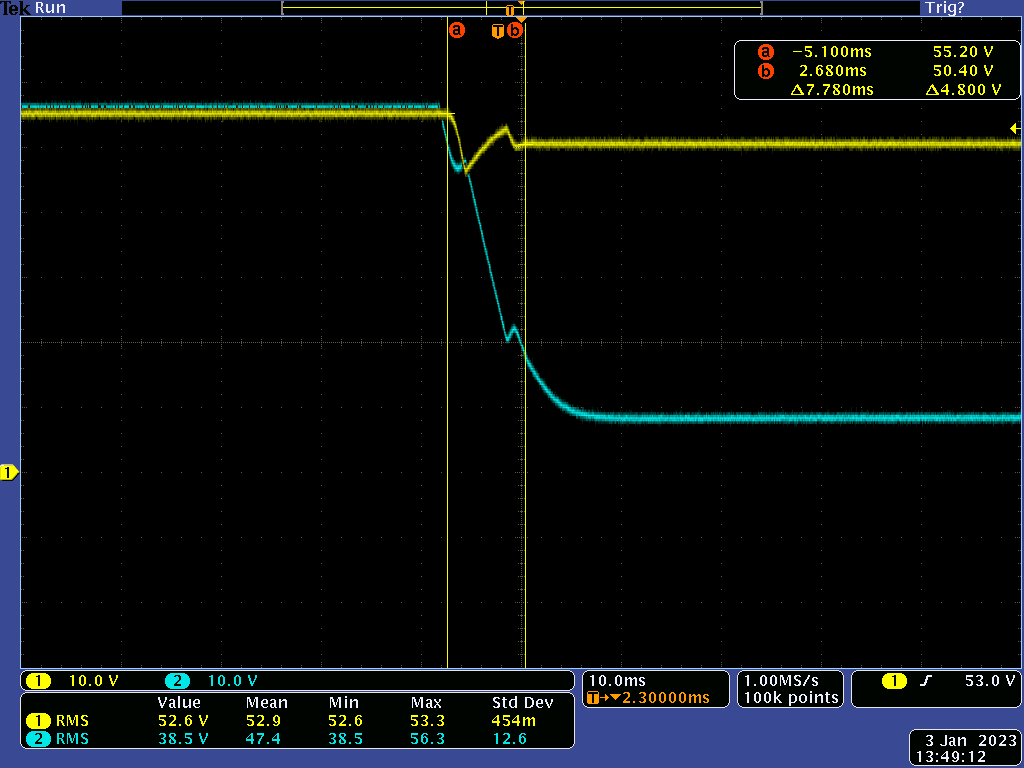
This trace shows overall response with a static 4A load. CH1=Vin, 2=Vout. At cursor A the input impedance changes from 0.3 to 2 ohms. The MPP loop's overall response is just under 8mS and is reasonably damped.
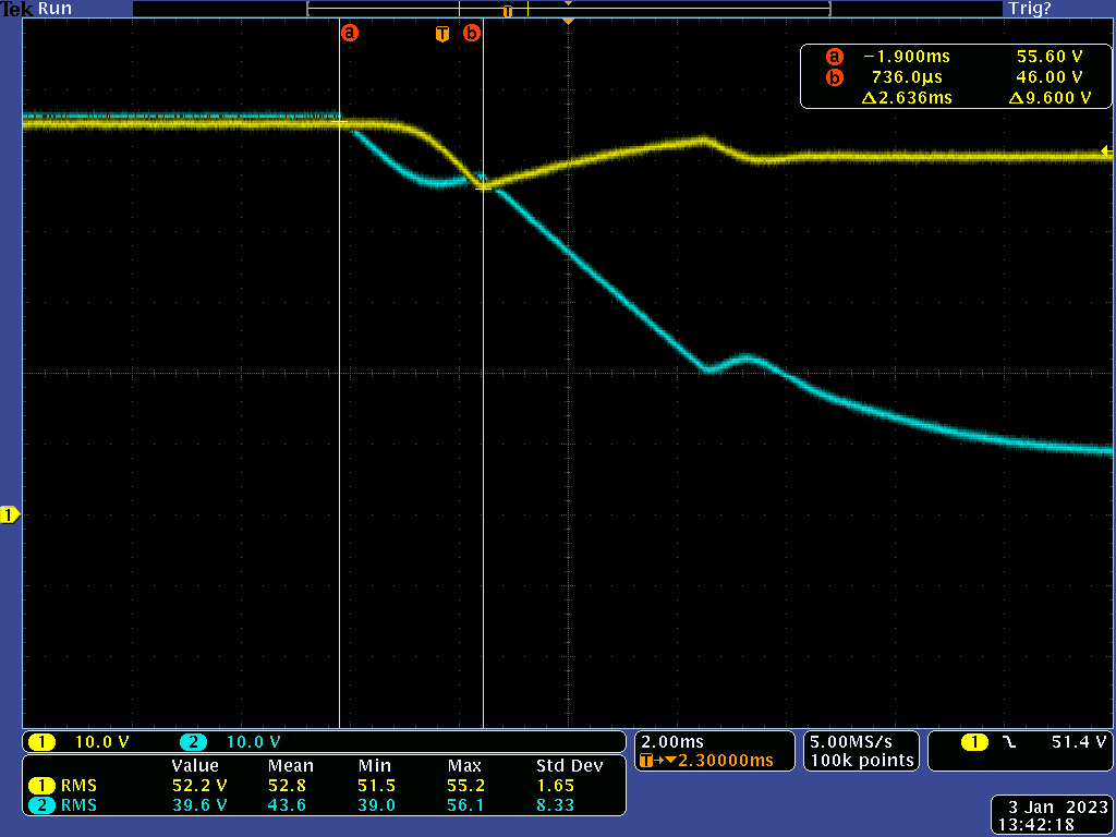
Same test but faster time base with cursor measuring loop's response before recovering to MPP value. Nothing to write home about but for MPP tracking I think this is decent.
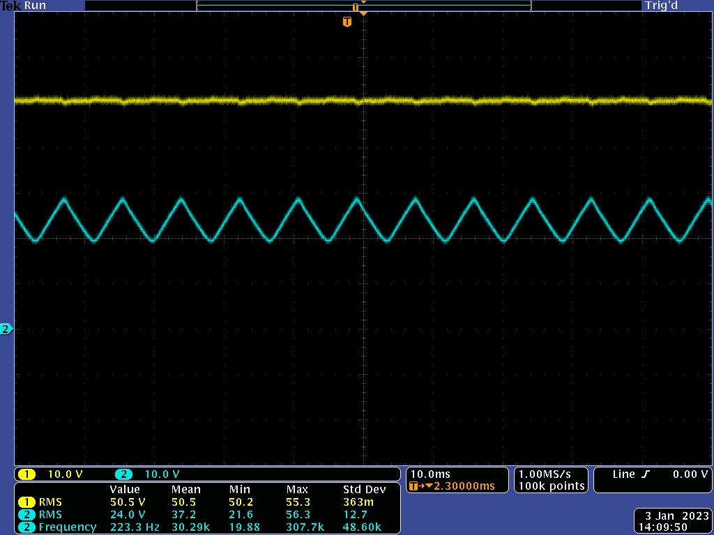
This trace shows MPP loop stability with a 120Hz impedance transient (1->4->1 ohm) applied to the converter's input. Vin holds steady at the MPP value with slight ripple.
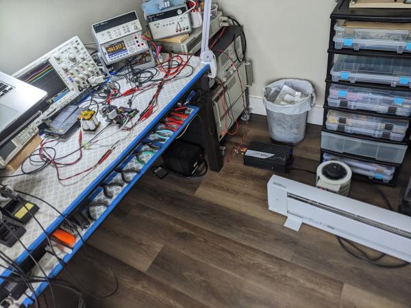
The acid test is how it performs with a real-world load. For this I connected a 48V DC -> 120V AC inverter to the converter. In turn, the inverter powered a 1.5kW space heater via an auto-transformer that allows me to control the AC load. The power supply for the converter was set to 57V with a 3.3A current limit. The inverter will place a time varying (sine) load on the converter and by applying enough AC load the input power supply's voltage will drop to engage the MPP loop.
The only difference between this and a 'production' installation is the absence of a battery bank connected to the charger's output. This was intentionally omitted to place additional work on the MPP loop.
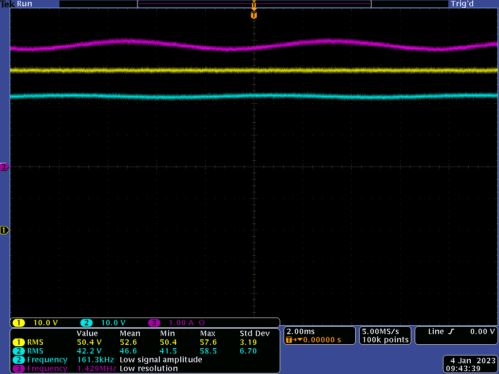
CH3 is the converter's output current - note that it is sinusoidal but Vin (CH1) to the converter is steady. Output power is ~ 160W.
This work shows that it is possible to implement a fast & stable analog MPP control loop that extends the capability of low-end, MCU, controllers. This scheme can be digitally enhanced by driving the circuit's Vref with a DAC output to vary the tracking value as well as an Enable feature for different modes of operation.
Discussions
Become a Hackaday.io Member
Create an account to leave a comment. Already have an account? Log In.