 davedarko
Disclaimer: I have never before done anything with LCDs directly
There are three things that I've learned, that are essential to drive an LCD segment. For easier understanding just think of one segment with 2 pads or legs that you have access to.
- There's a threshold voltage difference to achieve, where displays turn dark.
For example the LCD in the watch needs either 3V or -3V and it activates.
- The bias needs to be at 0V
When you toggle your segment on one pin between 0V and 3V, the display is held at a bias of 1.5V - something displays don't like. What you want to to is something like this, to hold the bias at 0V:PIN1 PIN2 Voltage 0V 3V 3V 3V 0V -3V
- You need to oscillate
Running a single segment correctly means you could use a good old 555 timer, set it up to ring at 60-90Hz (need to check for correct frequencies) and use an inverter for the second pin for the right way to keep your LCD healthy.
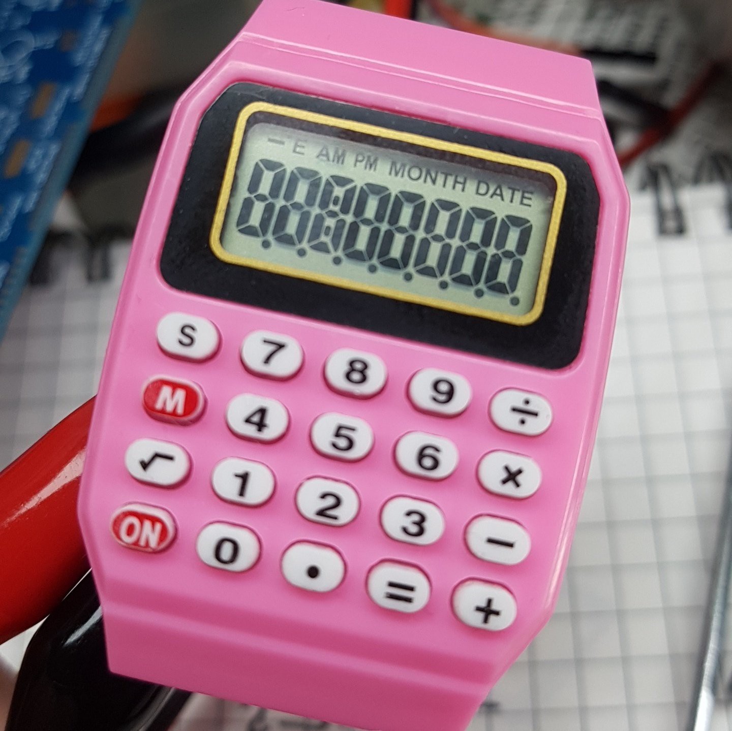
The Watch LCD
While I had it open for the first time, I accidentally had the power supply set to 2V and I was greeted with all the digits I can get. This threw me off so much that I thought the display would only run on 1.5V and any voltage above would lead to the display showing everything. So here I thought the SAML22 is out of the question, as it has a minimum voltage for the LCD of 2.4V. But it's a little bit more complicated than that!
I am one of those privileged humans with an oscilloscope, so I thought I might give it a quick look and see if the display really runs with 1.5V or rather wants something like 3V and the magic blob also does some voltage boosting. So I sanded away the solder stop mask from the vias on the board and soldered on some LED legs to connect the probes to.
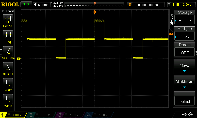
On the screenshot above is the voltage difference shown between one of the common segment pins and battery minus. First let's point out the obvious, this is between 0V and 3V, which is great news for using the SAML22! What you see here though is implicating a 1/4 duty wave with bias steps of 1/2 (what?).
The LCD has 4 of those common pins and 18 pins for segment quadruplets. You can probably spot the little indents that separate the long line into 3 areas, those are "timeslots" for the other common pins basically.
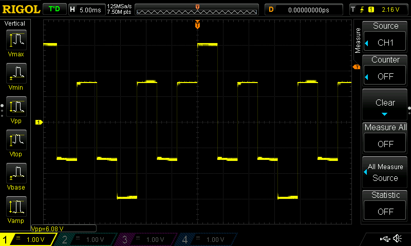
Above now is a screenshot of the voltages between one of the common pins and one of the segment pins. Here you can see Rule 2 being followed by having it oscillate around 0V. All the wavy stuff is really confusing though, just by looking at it, right? The important information for us is that the segment is activated, because we have a peak to peak voltage of 6V, meaning the segment is triggered by the 3V difference we talked about in Rule 1.
So what's the wavy stuff all about?
I don't really now :D but the SAML22 datasheet says that a "bias of 1/3" is preferred for a duty of 1/4. Reading further in the datasheet this means that you generate a step-wave of 1/3, 2/3 and full VLCD to talk to your LCD. The watch controller seems to use a bias of 1/2 for generating a "wave", that's why we see a step at 1.5V in the first scope screenshot. It's somehow necessary for multiplexing and keeping it AC.
SOURCES
- "Multiplex Drive and Bias of LCD Technology" - pacific display devices
https://www.pacificdisplay.com/lcd_multiplex_drive.htm - "EEVblog #1044 - LCD Technology Tutorial" - Dave Jones
https://www.youtube.com/watch?v=mo4_5vG8bbU - "EEVblog #1045 - How To Drive an LCD" - Dave Jones
https://www.youtube.com/watch?v=ZP0KxZl5N2o
Discussions
Become a Hackaday.io Member
Create an account to leave a comment. Already have an account? Log In.