Aaed Musa
Files
This project is fully open source. All digital files relating to this project can be found below in the files section. Here are all the files that I have included.
- Bill of material (with links and prices)
- All STEP files
- All the Arduino Libraries I created
- All Arduino programs
- Inverse Kinematic Diagrams and Formulas
- Electronic schematics
- Servo Motor Specifications with measured Torque, speed and power values.
- Images of electronic modifications not reflected in the schematics.
Initial Actuators
My first goal for this project was to create the electronic robotic actuators. This is easily the most vital part of the robot as it is what gives it functionality. This took up most of the project time as I wanted to get it correct before building or even designing the robot. I initially used a 360kV brushless motor to create my actuator. I created several designs that I each printed tested and modified to see if it would be a viable component to a quadrupedal robot. I designed planetary gearboxes and cycloidal gear drives to drive the actuators and increase torque. They all worked but in the end I never used a single one of them. This is because they each failed in a certain aspect. Quadrupedal actuators need to be high in torque, speed, and backdrivability. Long story short, I never fully achieved all of these simultaneously with all of my designs. This took about 6 months of my time which was not in waste at all, because it allowed me to learn a lot about cycloidal drives, planetary gear sets and actuators in general.
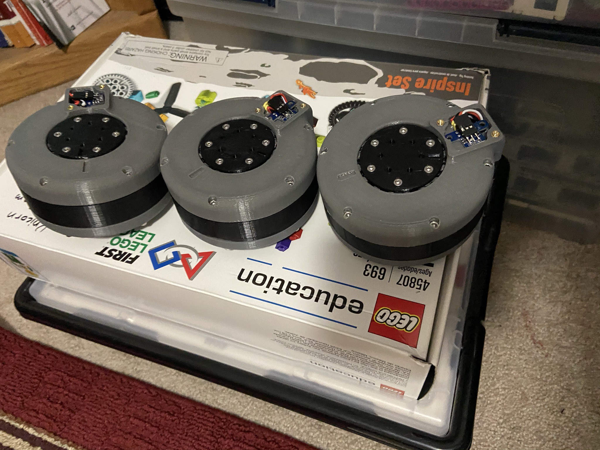
Servo Actuator
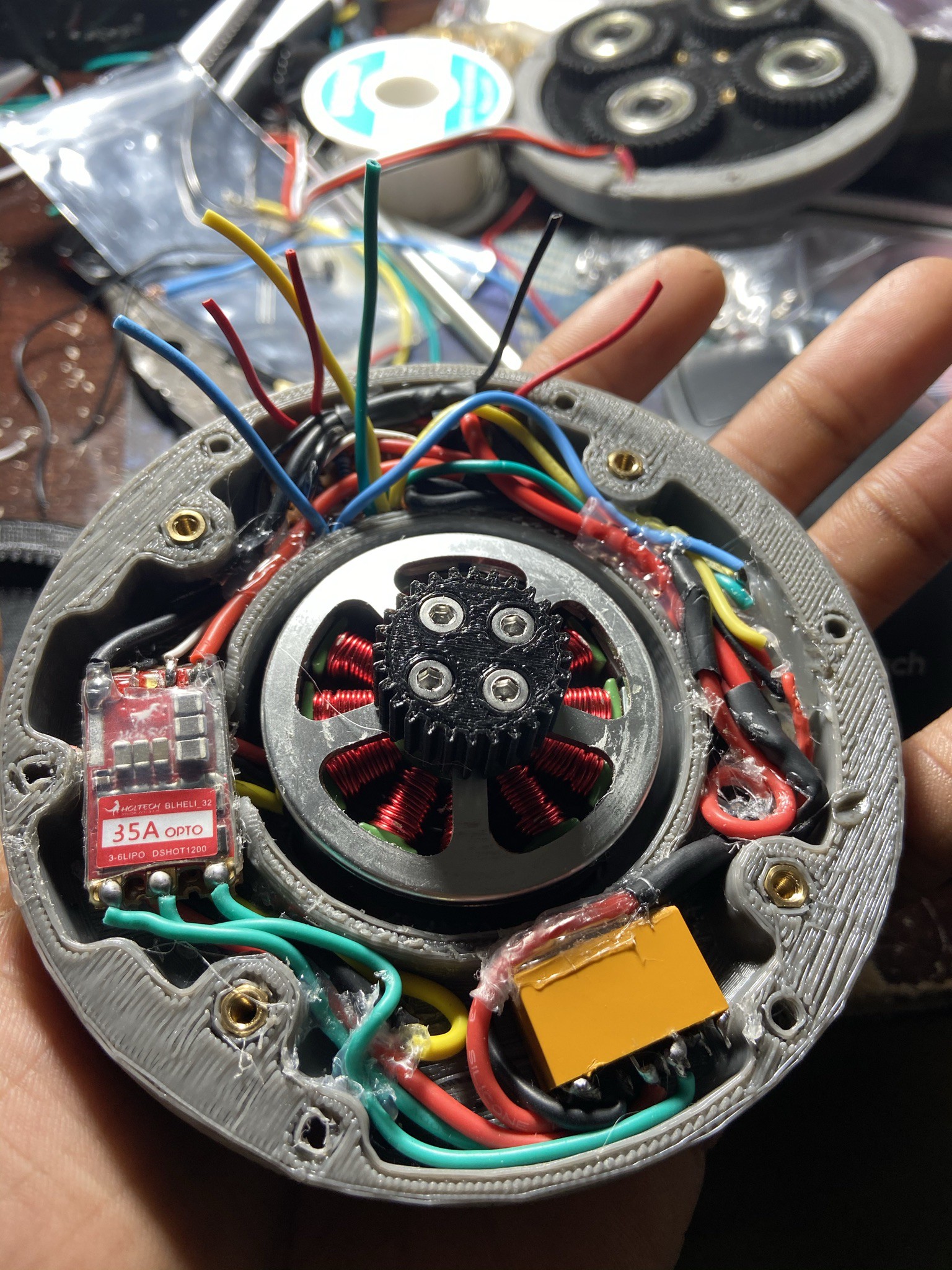
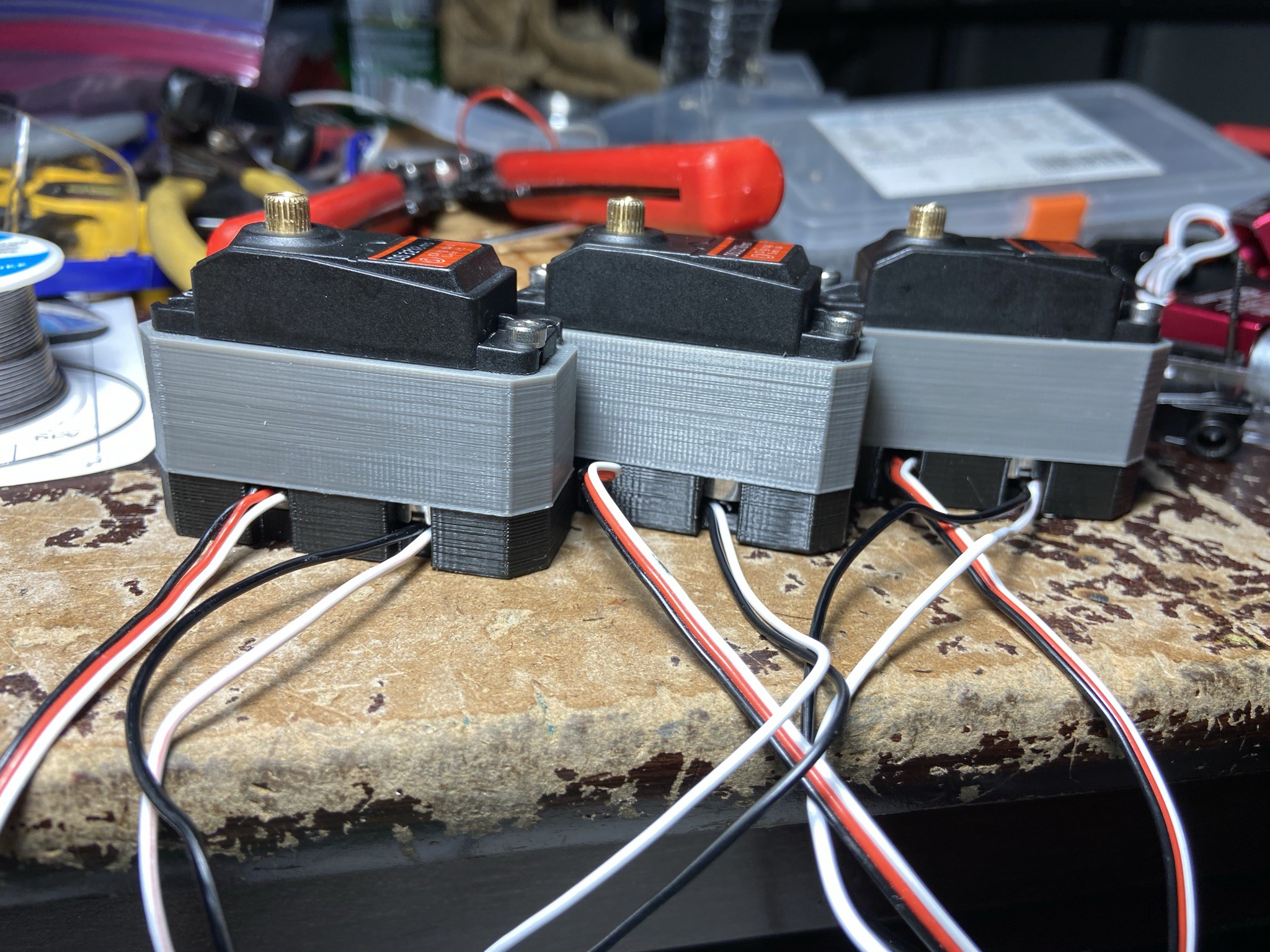
After coming to the realization that none of my actuators would work I turned to another approach, Servo motors. These motors used in several RC vehicles were the perfect candidate for my actuators. They are light, high in torque, high in speed, and fairly backdrivable. I purchased some coreless 35kgcm servos and tested them out. I chose coreless servos because they provided more torque and higher speed. To my liking they worked very well. Although they were great I still did wan to add some of my own modifications to make them operate as actual actuators and not just Servos. Most Servos can only move less than 360 degrees and those who don't cannot move accurately. Actuators have position feedback allowing them to move precisely so I decided to add absolute encoders to the servos. The first thing I did was design a new casing for the motors to rest in, so I opened one of the servos, took some measurements and designed a new case that got rid of the potentiometer in the Servo and equipped it with an absolute encoder and diamagnetic encoder magnet. I also attached a voltage divider in plate of the potentiometer so that the servo could run continuously. Best of all, this designed was pretty much the exact same size as the original servo and approximately the same weight. The only major difference was now it was enhanced with position reading capabilities and could travel 360 degrees. With this design these new Servo Actuators have potential to be used for purposes other than those of a common hobby servo. In addition this design can be used for all DS styled servos and not just the ones I used. After creating my actuator I decided to program it to utilize its position feedback capabilities.

Programming Position Control (Arduino Library)
The next Step after creating the actuators was to program them. I decided to create an Arduino Library so that I could use the position control features in other programs. The library essentially allows the actuator to move to a certain position (0 to 360 degrees) or for a certain displacement (0 to infinity degrees). Along with this, the library allows you to control the max speed of the actuator (on a scale of 0 to 100), the acceleration constant of the actuator (which controls how fast it accelerated), and the direction the actuator moves. The program to make the actuator move precisely is simple. The servo is connected to a PCA9685 board which allows you to control up to 16 servos through the I2C communications protocol. Given that the Servo Actuator does not have the potentiometer it once did and can now move 360 degrees the servo can be moved by simply calling a writeMicroseconds function and inserting a value from around 1000 to 2000 with values from 1000 to 1500 moving the servo one way and values from 1500 to 2000 moving it another. It should be noted that a value of 1500 should stop the actuator but each actuator differs and can be stopped by other numbers close to 1500 such as 1490, 1510 etc... Doing this is the program simply moves the actuator but for to stopped at its directed position I utilized a P algorithm. This is just a PID algorithm without the Integral and Derivative terms. Here is a step by step description of what the Library does.
- Receives input position target
- Enters into Loop where actuators pwm value is calculated
- Calculates pwm output throughout loop by multiplying error (target count - current count) to the given acceleration constant
- Exits loop once target count/position has been reached.
When this program is executed the Servo actuator should gradually decelerate until it reaches its target position. The library also has options to calculate and display the velocity of the actuator, and the position of the actuator.
Here is a snippet of the code which shows how to setup the actuator and functions that can control it.
#include "Actuator_Control.h"

//define individual actuators (max of 12 actuators). The order of the defined actuators is their assignment when using an assembly.

//pin assignment: (pin number, encoder pin, invert (ON/OFF), offset, stop pwm (close to 1500), switch polarity(ON/OFF))
Actuator Actuator(0, A0, OFF, 0, 1500, OFF); //Define actuator 0

//Define actuator assembly to run multiple actuators simealtaneously (max of 1 assembly)
Assembly Assembly;

void setup() {
  //Start the serial monotor to see potential errors
  Serial.begin(115200); //baud rate
  Assembly.start();
  delay(1000); //short delay to read initial data properly
}

void loop() {
  /*
    //Single Actuator Commands
    Actuator.movePos(90); //move to a certain position
    Actuator.moveDispl(90); //Move for displacement
    Actuator.moveDynamic(90); //use in a loop to constantly move the actuator to a certain position (dynamic movement)
    Actuator.getPos(); //gets the current angle of an actuator
    Actuator.setMove(0.1, 100, CW); //enter acceleration constant, max PWM value (on a scale from 0 to 100) and direction (CW, CCW, or SHORTEST)

    //Multiple Actuator Commands
    Assembly.set(); //starts the I2C and stops all actuators
    Assembly.movePos(90, 0, 0, 0, 0, 0, 0, 0, 0, 0, 0, 0); //move to a certain position
    Assembly.moveDispl(90, 0, 0, 0, 0, 0, 0, 0, 0, 0, 0, 0); //Move for displacement
    Assembly.moveDynamic(90, 0, 0, 0, 0, 0, 0, 0, 0, 0, 0, 0); ////use in a loop to constantly move the actuator to a certain position (dynamic movement)
  */
}
Here is a video of a position mapping function I added to the library. It copies the position of an input position, in this case that is the potentiometer I'm moving with my hand. This could also be used with another actuator since I can also measure the position of the actuator as well as control it. This could allow for something similar to bilateral teleoperation seen with much more powerful actuators.
Torque and Speed Testing (Evaluating the Specs of the Servo)
After creating the actuator, and making a library to control it naturally I conducted some torque and speed tests. It should be noted that I did not change any components of the motor or of the gearing of the Servo actuator so the results of these tests are akin to the original 35kg coreless Servo itself. I did two tests and measured 2 things in each. I did a torque test where I measured the stall torque and stall current of the Servo Actuator. I also did a speed test where I measured the speed of the actuator and the no load current. I also measured the gear ratio of the servo just for my reference of how powerful the coreless motor is on its own. Here are my results (the excel table is also given in the files).
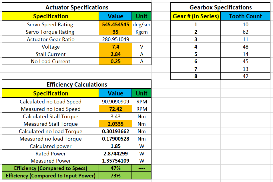
From the tests we can see that the Servo Actuator is less than 50% as efficient as it claims to be, and about 73% as efficient compared to the power supplied. It resembles the ratings of a 20kg Servo more than a 35kg Servo. This comes to show just another reason why I chose a 35kg servo. Choosing a servo with a 20kg rating, for example, could have resulted in it perhaps having an actual rating of a 12kg servo. It's unlikely that any servo will ever lift up to its torque ratings, which is why I over compensated by getting a servo rated for 35kg. Its measured close to a 20kg servo which is still plenty of torque for its size, considering my previous actuator designs produced the same amount of torque but weighed over 4 times as much. Also considering that the specifications for this servo had a higher power rating than the actual input power, also shows that these specs are not accurate.
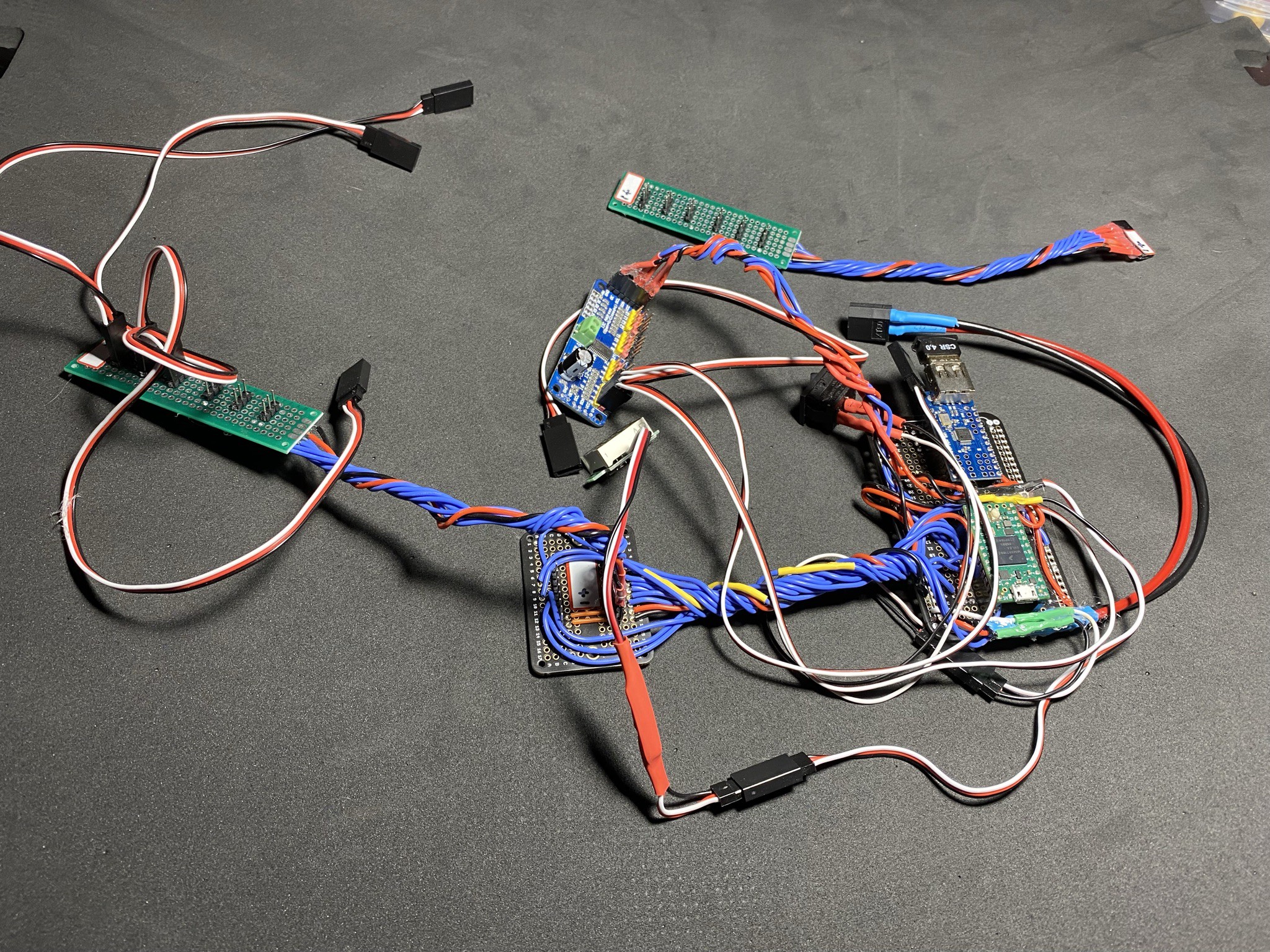
Electronics
I tried to keep electronics to a minimum in this project. I wanted to use the smallest amount of electronics possible so that I could fit them all in a small space. There were 24 components that needed to be connected to a microcontroller on this robot. 12 of these were the pwm pins on the Servo motors, and the other 12 were the corresponding absolute motor encoders that needed to be connected. I decided to connect the absolute encoders directly to the microcontroller, and I used a PCA9685 servo driver board to communicate to all of the actuators via an I2C bus. This way I only used 14 (12 from the encoders and 2 an SCL and SDA pin for the I2C bus) pins on the microcontroller instead of 24. I also decided to use a Teensy 4.0 board since it was small, and extremely fast. Besides the actuators and encoders, the only other electronic connected to the microcontroller was a mini USB host shield. These are developed mainly for arduino boards and they allow you to plug in a Bluetooth dongle and use a PS4 controller, and other controllers, with your microcontroller. I used a PS4 controller with it, and I found it to work quite well. I also created an arudino library with functions to use the PS4 controller and receive feedback from the joysticks, and buttons.
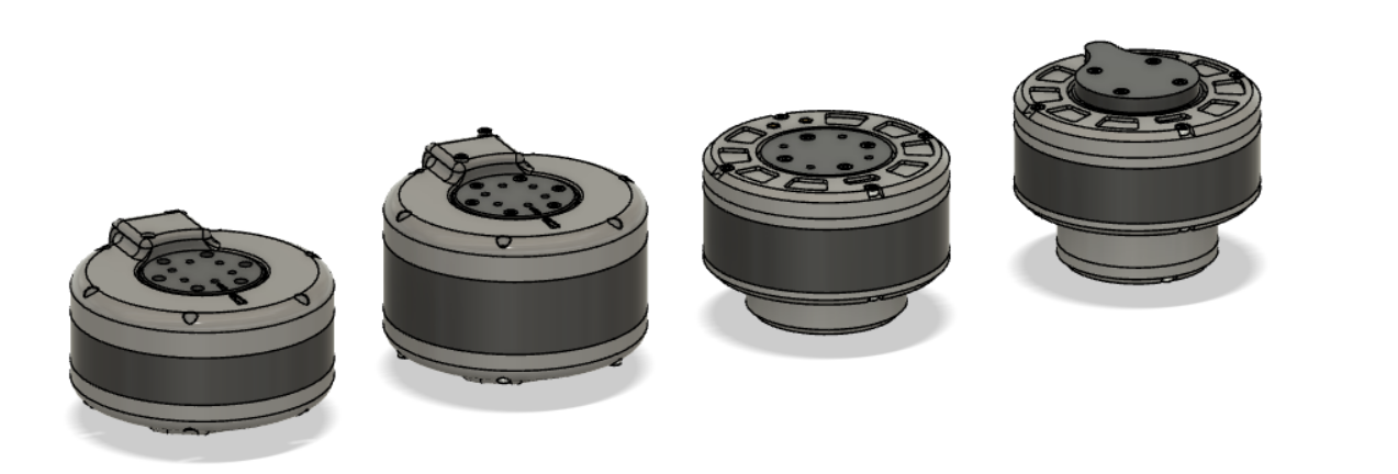
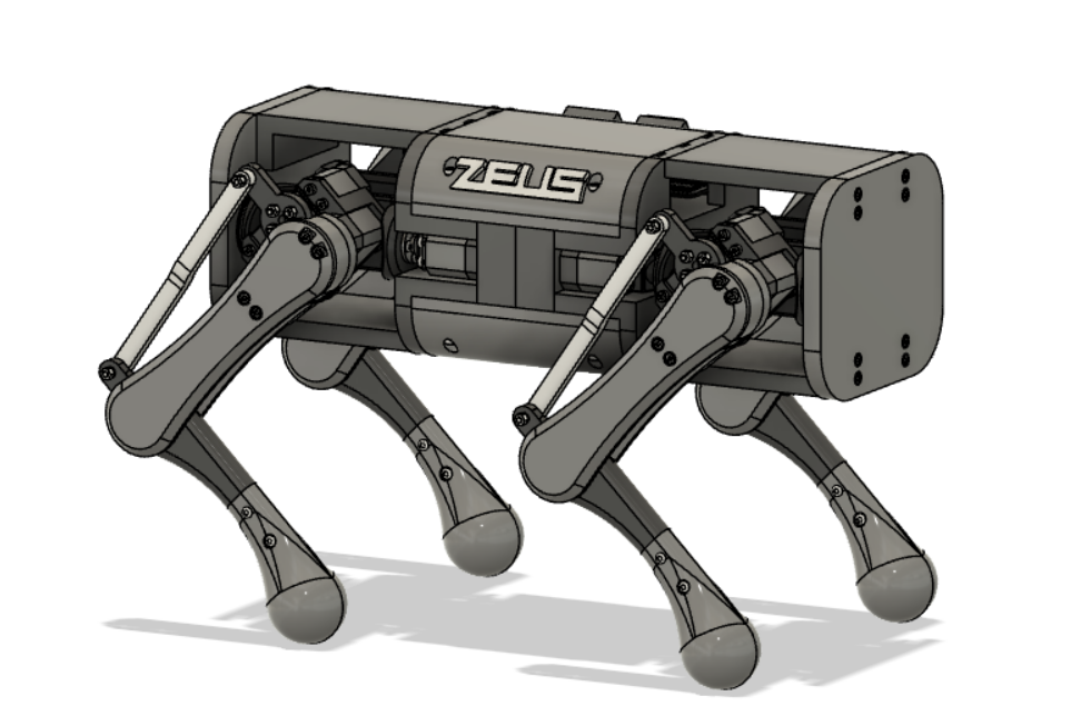
Robot assembly
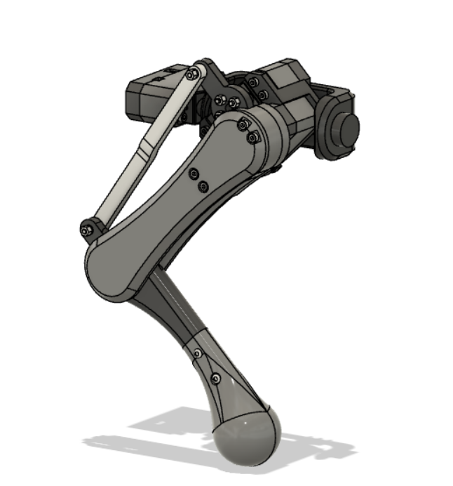
My next step after creating the actuator and performing all tests on it was to design the robot itself. Using the CAD software Fusion 360 I created 3 linked models. The first was the aforementioned Actuator design, the next was a single leg assembly for the robot, and the last was the robot itself. These were each dependent on the previous. The single leg assembly model was linked to the actuator model, and the robot was linked to the the single leg assembly and the actuator design. This way whenever I made changes to any of the models, the other would update so I didn't have to go back and make the manual changes. This saved me lots of time since I made many slight modifications during the entire build. Once I finished my design for the robot I 3D printed all of the parts on my two 3D printers (a Creality - CP-01 and an XYZ Davinci Pro). Here are Images of my designs.
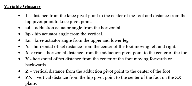
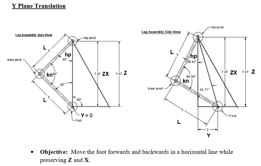
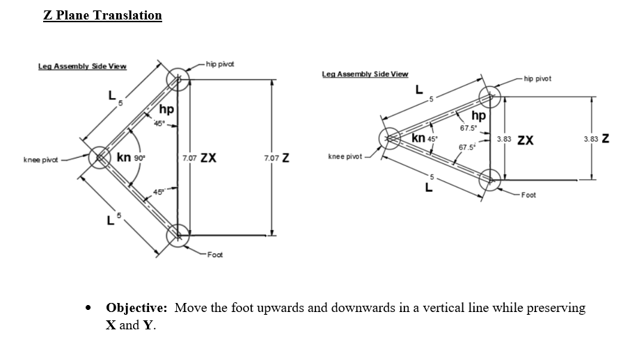
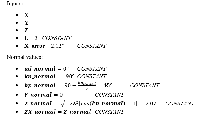
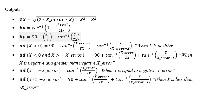
Inverse Kinematics
At this point in the project I started to create programs for the robot to function. The first thing I needed to do was derive inverse kinematic formulas to move each leg exactly where I wanted it. I derived equations to move each leg on a single axis given an input distance. For example if I wanted to move the leg forward, the equations I created would find the position to move the actuators in such a way that the leg moved forward but did not change make any changes to the other axis ie it did not move up or down, just straight in a single plane. After creating the formulas on paper, I then put them into Arduino and used the PS4 controllers analog joysticks as inputs to change the position of the leg. Here are the formulas I derived, what each axis does, and a bit of explanation as to what each variable is as well as their formulas.