 Aaed Musa
Files
This project is fully open source. All digital files relating to this project can be found below in the files section. Here are all the files that I have included.
- Bill of material (with links and prices)
- All STEP files
- All the Arduino Libraries I created
- All Arduino programs
- Inverse Kinematic Diagrams and Formulas
- Electronic schematics
- Servo Motor Specifications with measured Torque, speed and power values.
- Images of electronic modifications not reflected in the schematics.
Initial Actuators
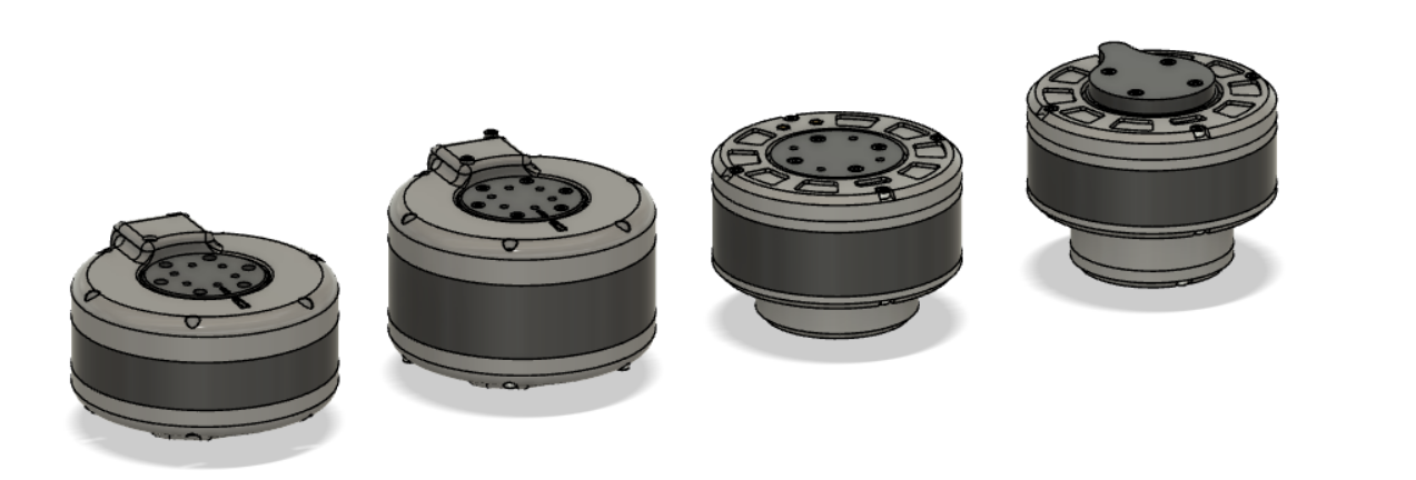
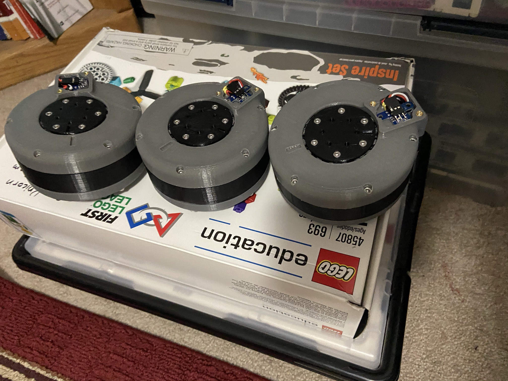
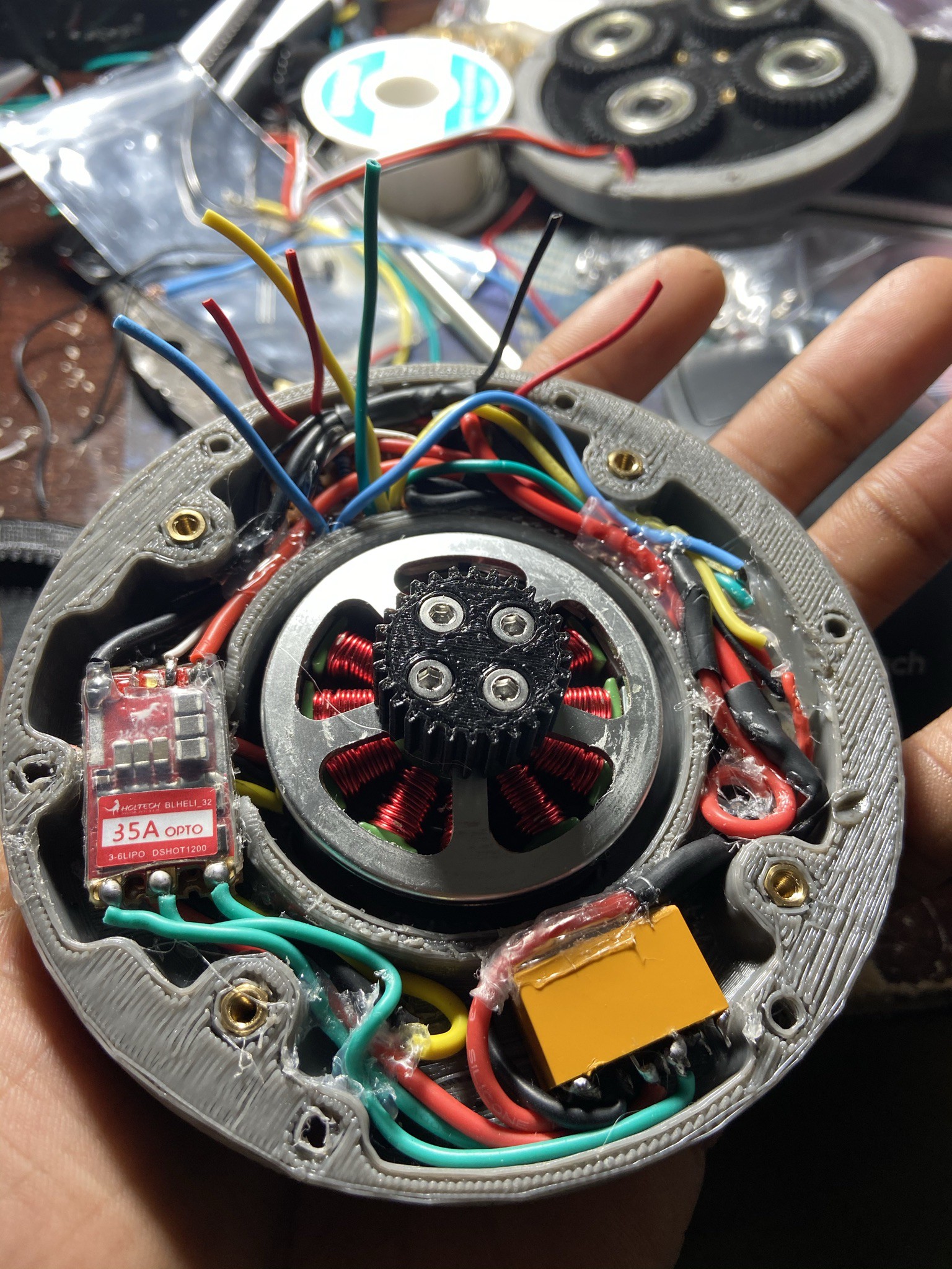
My first goal for this project was to create the electronic robotic actuators. This is easily the most vital part of the robot as it is what gives it functionality. This took up most of the project time as I wanted to get it correct before building or even designing the robot. I initially used a 360kV brushless motor to create my actuator. I created several designs that I each printed tested and modified to see if it would be a viable component to a quadrupedal robot. I designed planetary gearboxes and cycloidal gear drives to drive the actuators and increase torque. They all worked but in the end I never used a single one of them. This is because they each failed in a certain aspect. Quadrupedal actuators need to be high in torque, speed, and backdrivability. Long story short, I never fully achieved all of these simultaneously with all of my designs. This took about 6 months of my time which was not in waste at all, because it allowed me to learn a lot about cycloidal drives, planetary gear sets and actuators in general.
Servo Actuator
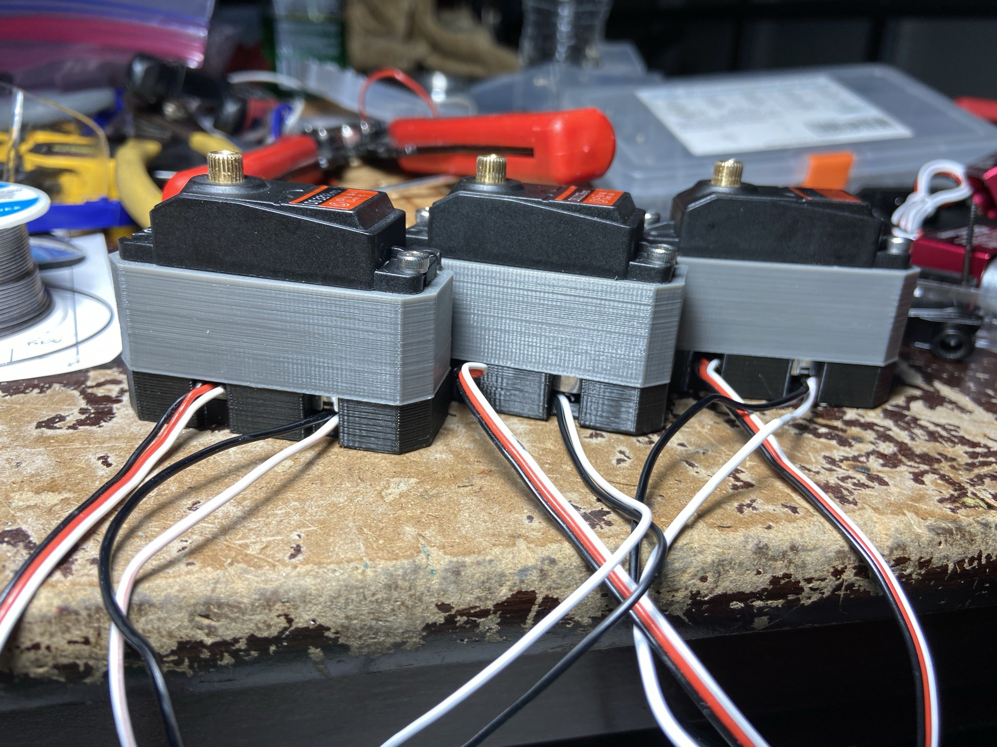
After coming to the realization that none of my actuators would work I turned to another approach, Servo motors. These motors used in several RC vehicles were the perfect candidate for my actuators. They are light, high in torque, high in speed, and fairly backdrivable. I purchased some coreless 35kgcm servos and tested them out. I chose coreless servos because they provided more torque and higher speed. To my liking they worked very well. Although they were great I still did wan to add some of my own modifications to make them operate as actual actuators and not just Servos. Most Servos can only move less than 360 degrees and those who don't cannot move accurately. Actuators have position feedback allowing them to move precisely so I decided to add absolute encoders to the servos. The first thing I did was design a new casing for the motors to rest in, so I opened one of the servos, took some measurements and designed a new case that got rid of the potentiometer in the Servo and equipped it with an absolute encoder and diamagnetic encoder magnet. I also attached a voltage divider in plate of the potentiometer so that the servo could run continuously. Best of all, this designed was pretty much the exact same size as the original servo and approximately the same weight. The only major difference was now it was enhanced with position reading capabilities and could travel 360 degrees. With this design these new Servo Actuators have potential to be used for purposes other than those of a common hobby servo. In addition this design can be used for all DS styled servos and not just the ones I used. After creating my actuator I decided to program it to utilize its position feedback capabilities.

Programming Position Control (Arduino Library)
The next Step after creating the actuators was to program them. I decided to create an Arduino Library so that I could use the position control features in other programs. The library essentially allows the actuator to move to a certain position (0 to 360 degrees) or for a certain displacement (0 to infinity degrees). Along with this, the library allows you to control the max speed of the actuator (on a scale of 0 to 100), the acceleration...
Read more »
 ProgressTH
 Luke J. Barker
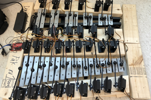
 Jason P.
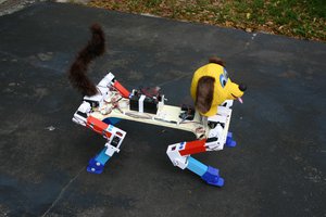
 Mike Rigsby