 Maximiliano Palay
This project has been selected as one of the 50 finalists in the Hackaday Prize 2021! A huge thank you to everyone that has supported the project in any way, and thank you to Hackaday for this incredible honor.
Robotics Ground Control Station Promotion video for Hackaday Prize 2021 finals
You can check the project logs for more detailed information.
Useful resources:
- Project logs (from the idea to the final product, plus tests, conclusions & next steps)
- Project files (CAD files, general views, high level schematics, BOM)
- Project Components
- Project Github Repository
- Project instructions (these are high level instructions to guide you through the process. For more detail, you can check the logs)
Before you start reading, let me tell you this was a huge overkill for the use I'd give it. The project objective wasn't only the product itself, but the process is something I enjoy and value very much.
Introduction
"UAV ground control station (GCS) is a land- or sea-based control centre that provides the facilities for human control of Unmanned Aerial Vehicles." - Wikipedia
Although I like the definition given above, it is specific for UAVs and I wouldn't limit this project only to UAV control, but also unmanned ground vehicles (UGV), among others.
The idea to make something like this came up when working on a previous personal project, the Cablecam. I saw the necessity to have a customizable, portable controller with enough power to run some over-average tasks such as inference using neural networks and at the time I made the following station.
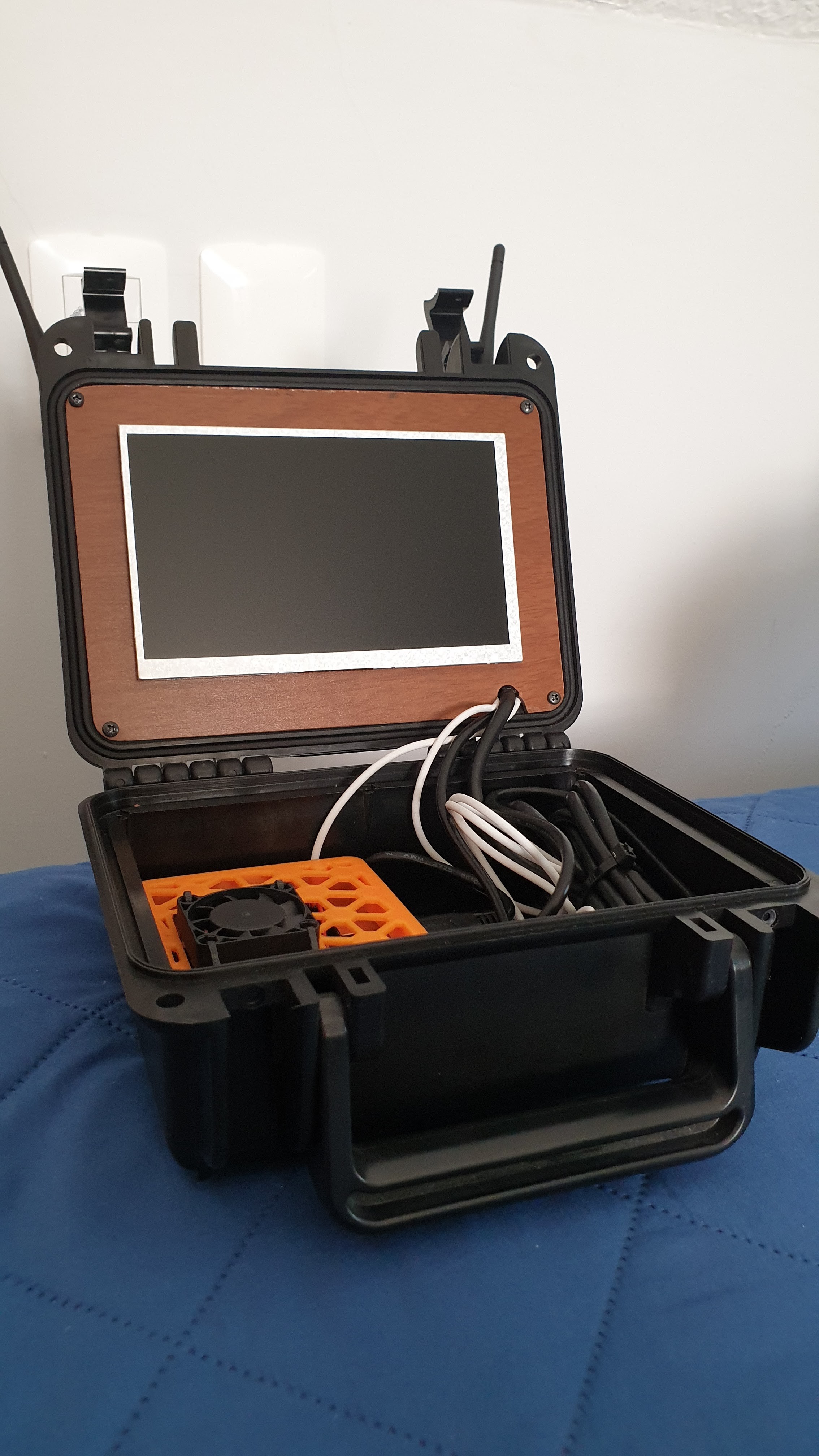
It was simple, consisted of a Nvidia Jetson Nano as the main brains, a 7" screen and two small wireless adapters (2.4GHz). When in use, I connected an Arduino to allow for inputs such as a potentiometer. It served its purpose, it allowed me to control the cablecam, receive a video feed and a bit of telemetry. It also ran inference on the video feed to detect persons in the frame and follow them. The whole thing was implemented in Python. It worked, but it was somewhat sketchy.
The main issue with this base station is it was impractical, each time I went to use it I had to bring a keyboard, an AC wall adapter, the Arduino (it wasn't installed inside due to space restrictions), and if I wanted to add more user inputs (joysticks, buttons, etc), it would become unusable. The wireless communication worked, but was a bit poor due to the WiFi adapters being low power and working in 2.4GHz (this frequency range is the one in which most WiFi networks work, Bluetooth, and microwave ovens too). It served its purpose, but I could do better.
To solve the issues with my previous attempt at a base station, I wanted to make something that had more of a finished product kind of feel, and due to my inability to make a dense integration of components, it should be bigger. It would use the same computer (Jetson Nano) and screen, but hopefully operate in a different frequency in the unlicensed or free use spectrum. It would have many integrated inputs such as joysticks, switches and buttons. To allow for easy interfacing it should have at least a couple USB ports and an RJ45 easily accessible.
Design
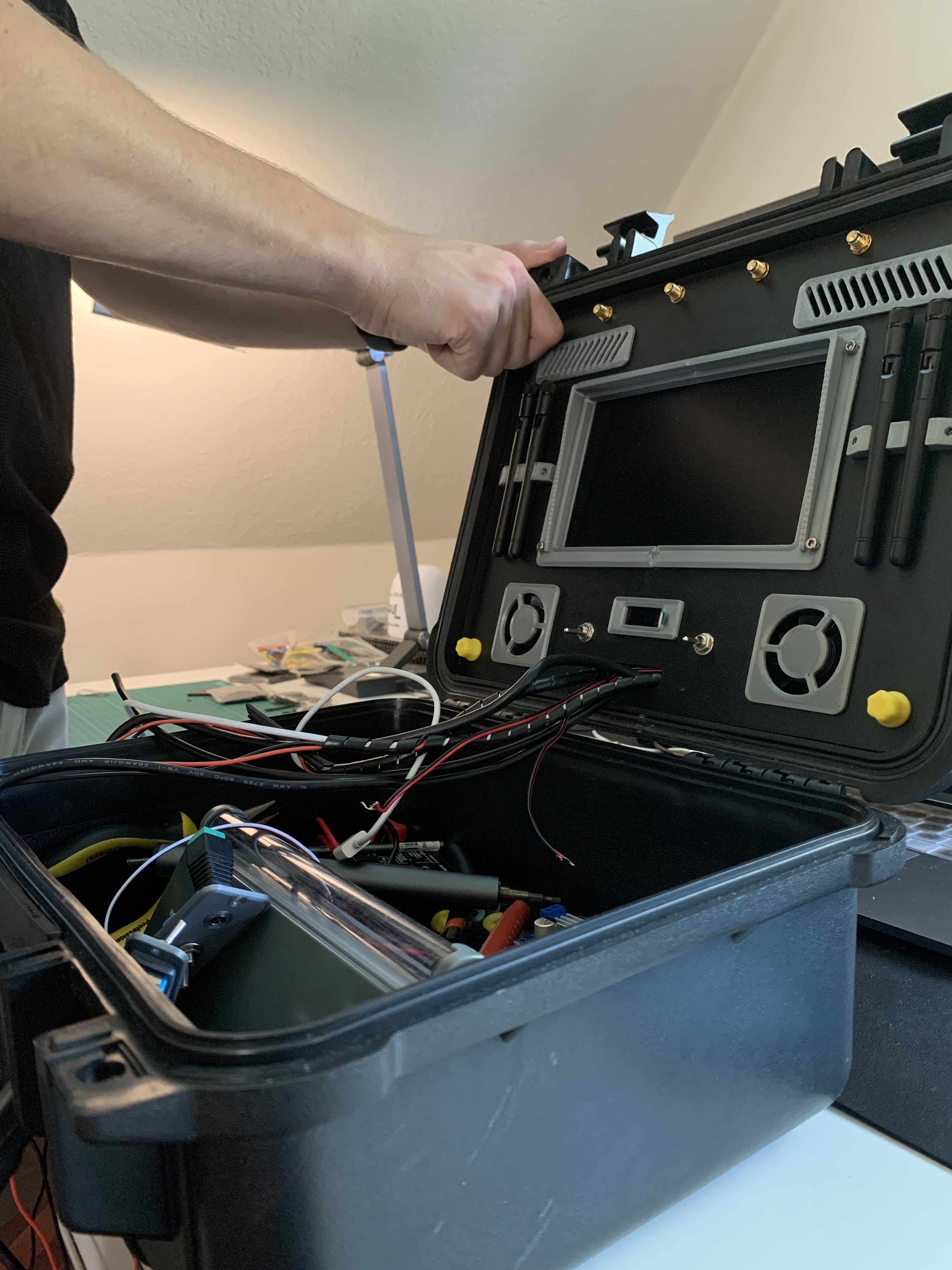
For this project I never considered anything else but a rugged, hard case. I wanted something simple, but functional and good looking. I had at my disposal a 3d printer at home and a CNC cutter at school, so having those manufacturing methods in mind, I got to work. Once I gathered all the components, I measured them and started designing.
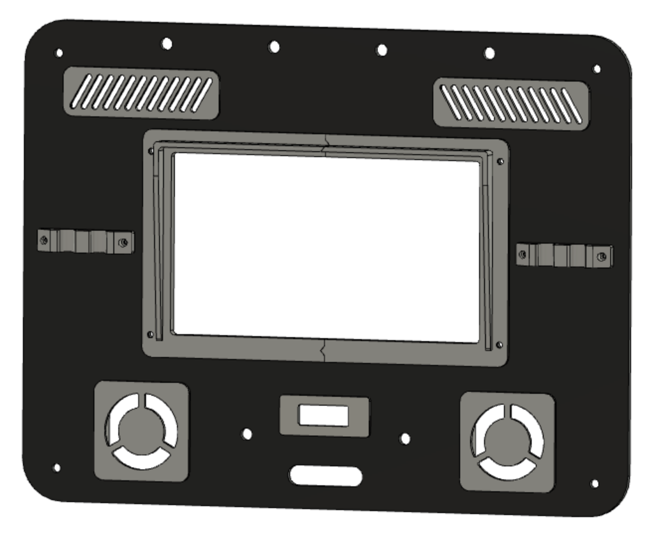
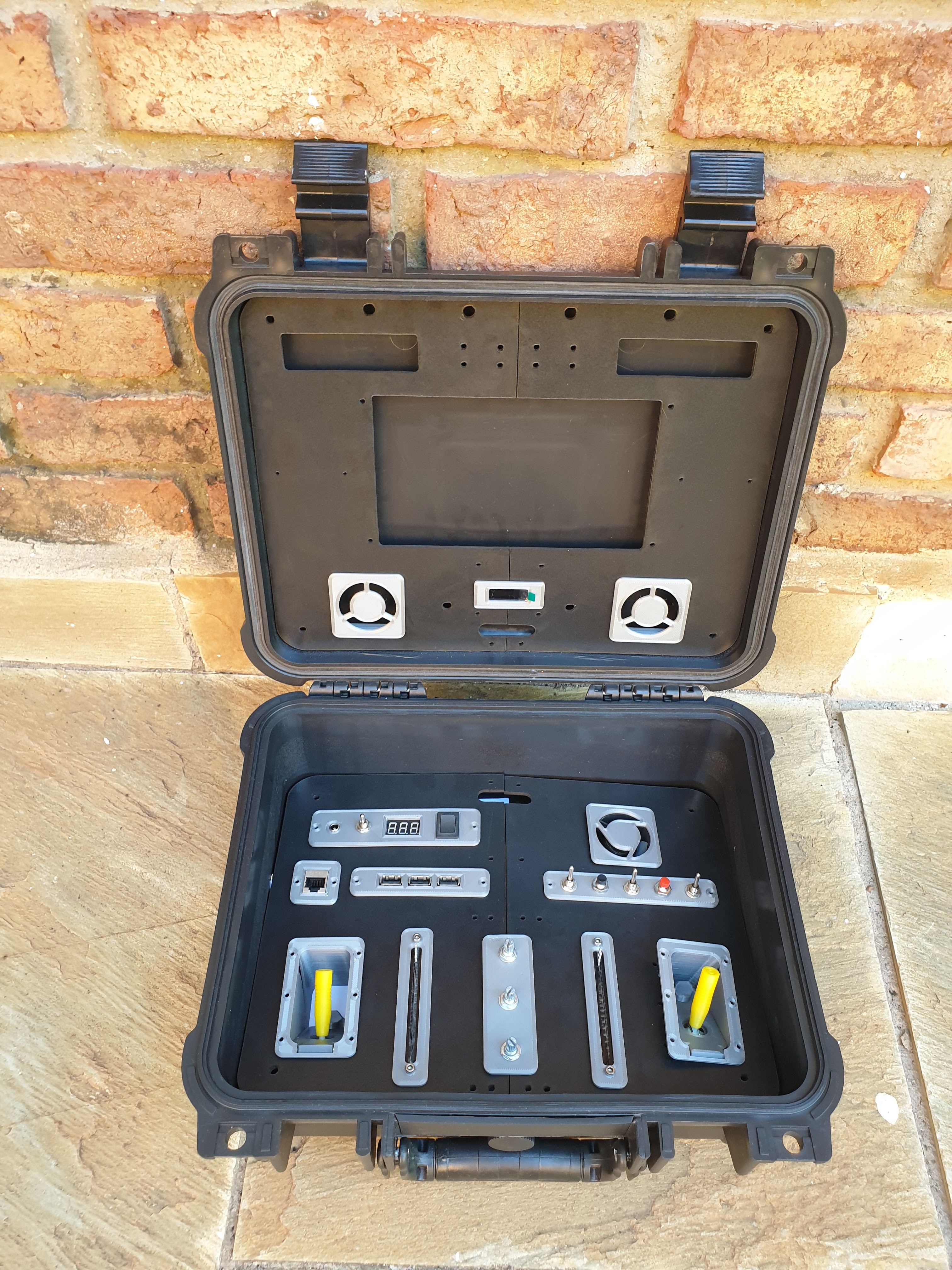
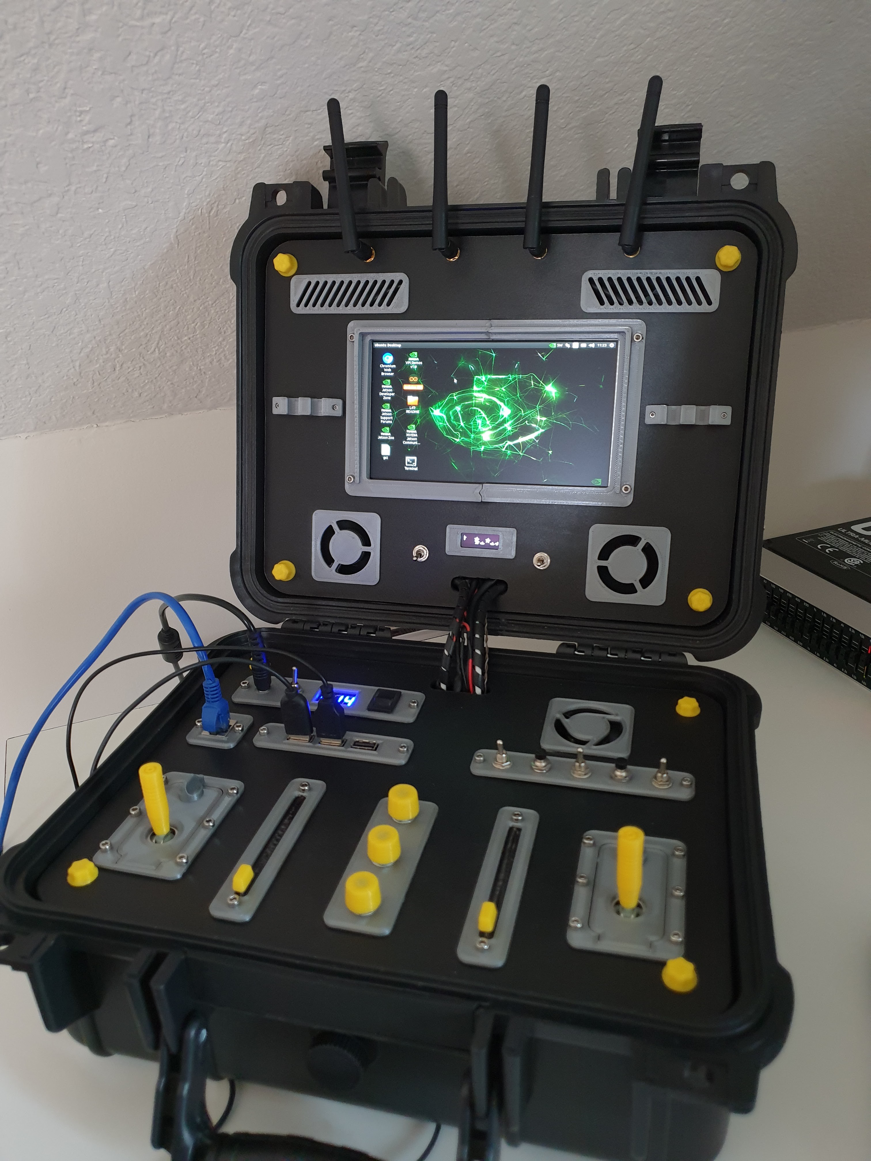
The hard case has much less space on the lid, so most components were placed on the bottom part. The lid holds a 7" screen, the two wireless adapters with respective power switches and antenna connectors, an auxiliary 0.91" OLED display, cooling fans and vents, and antenna holders.
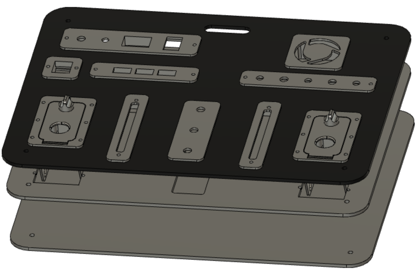
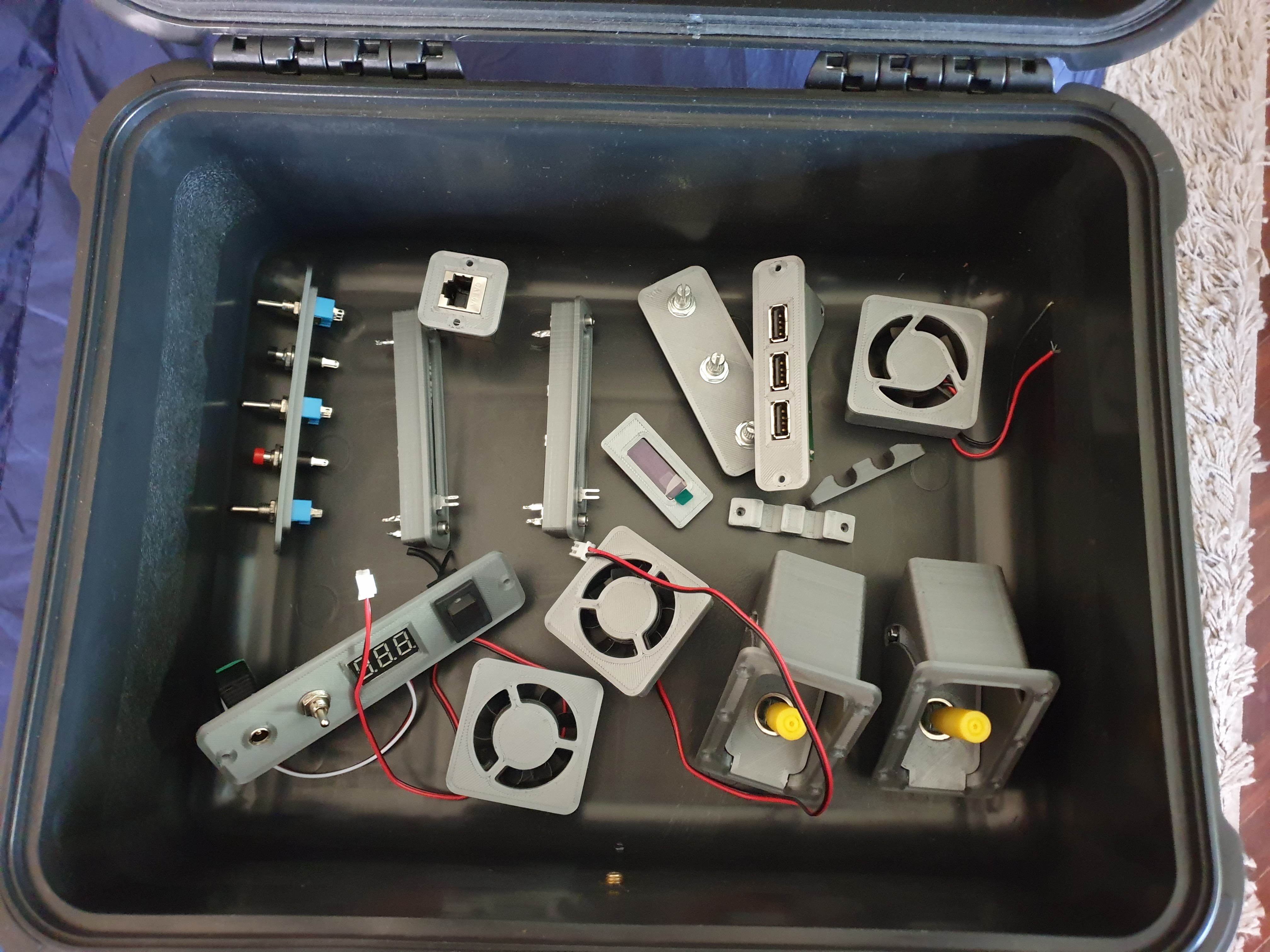
On the bottom piece I went for a stack design, having multiple panels stacked to allow for component mounting on multiple levels. I added switches, buttons, sliders, rotary potentiometers and 2 axis joysticks, as well as an RJ45 port, mounted the USB hub, a power input DC jack, an LED voltage meter and a cooling fan.
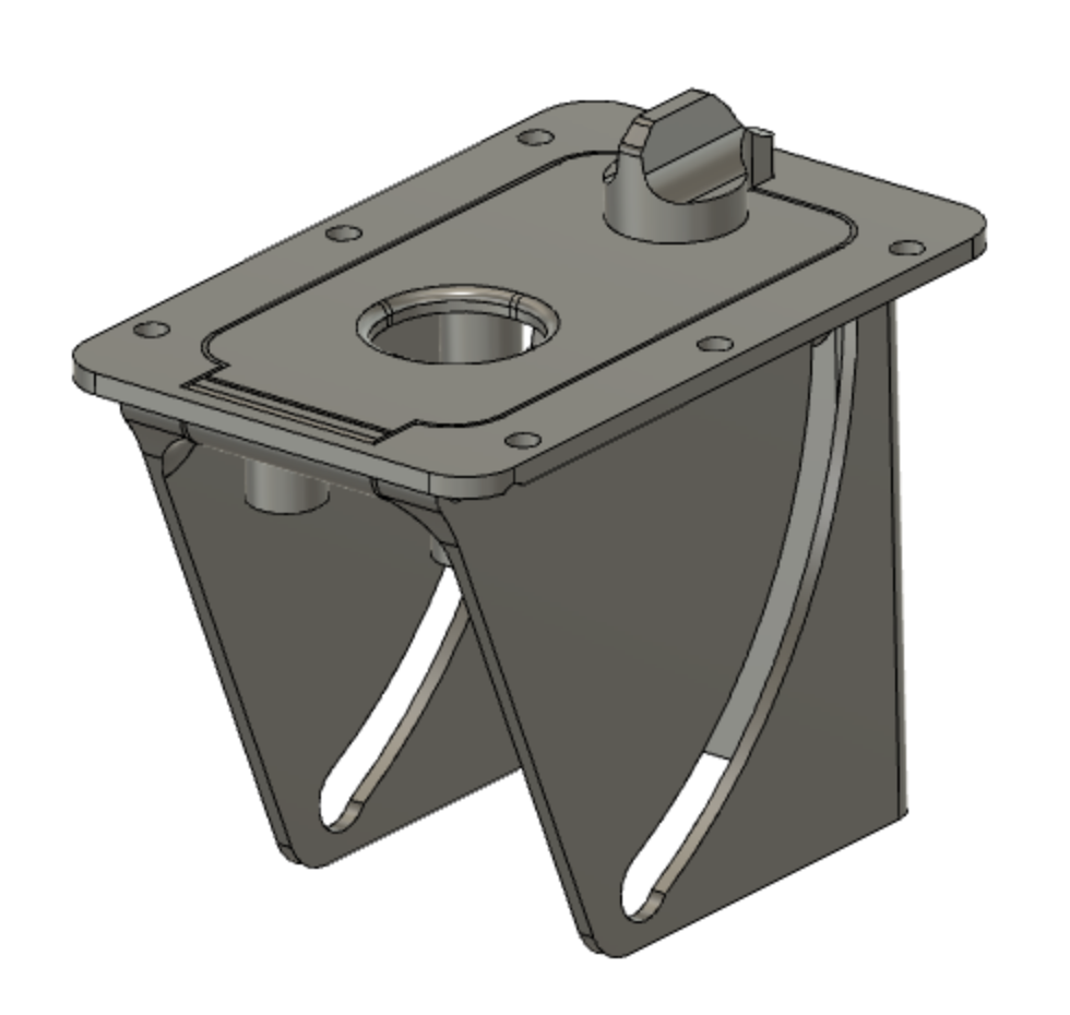
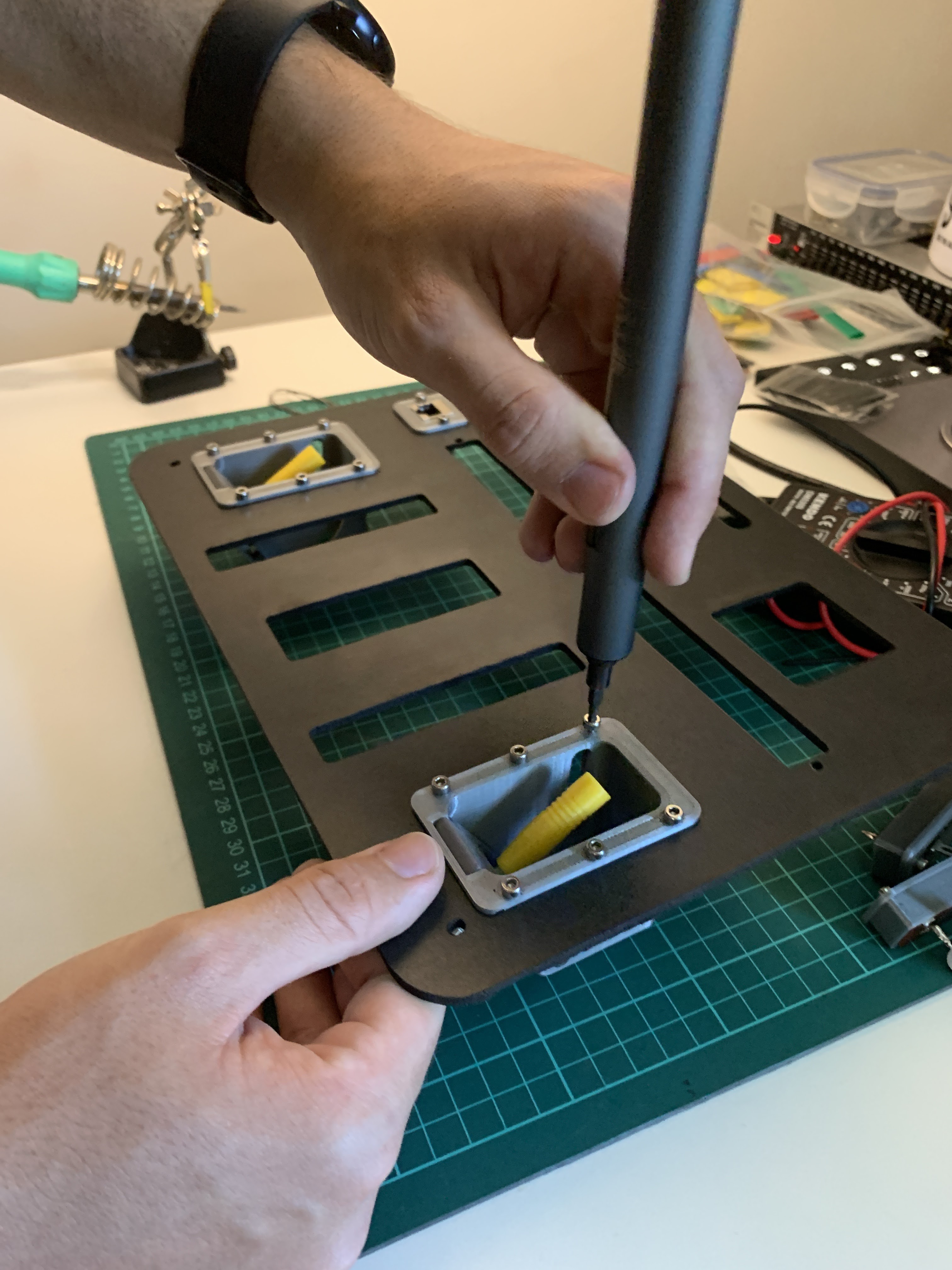
An interesting part of the design were the joysticks. In order to be able to have them in the position I wanted, these had to be retractable, so I designed a pivoting mechanism with a lock that allows the sticks to be folded down for transportation.
As usual, everything was designed in Fusion 360.
Manufacturing - making the parts
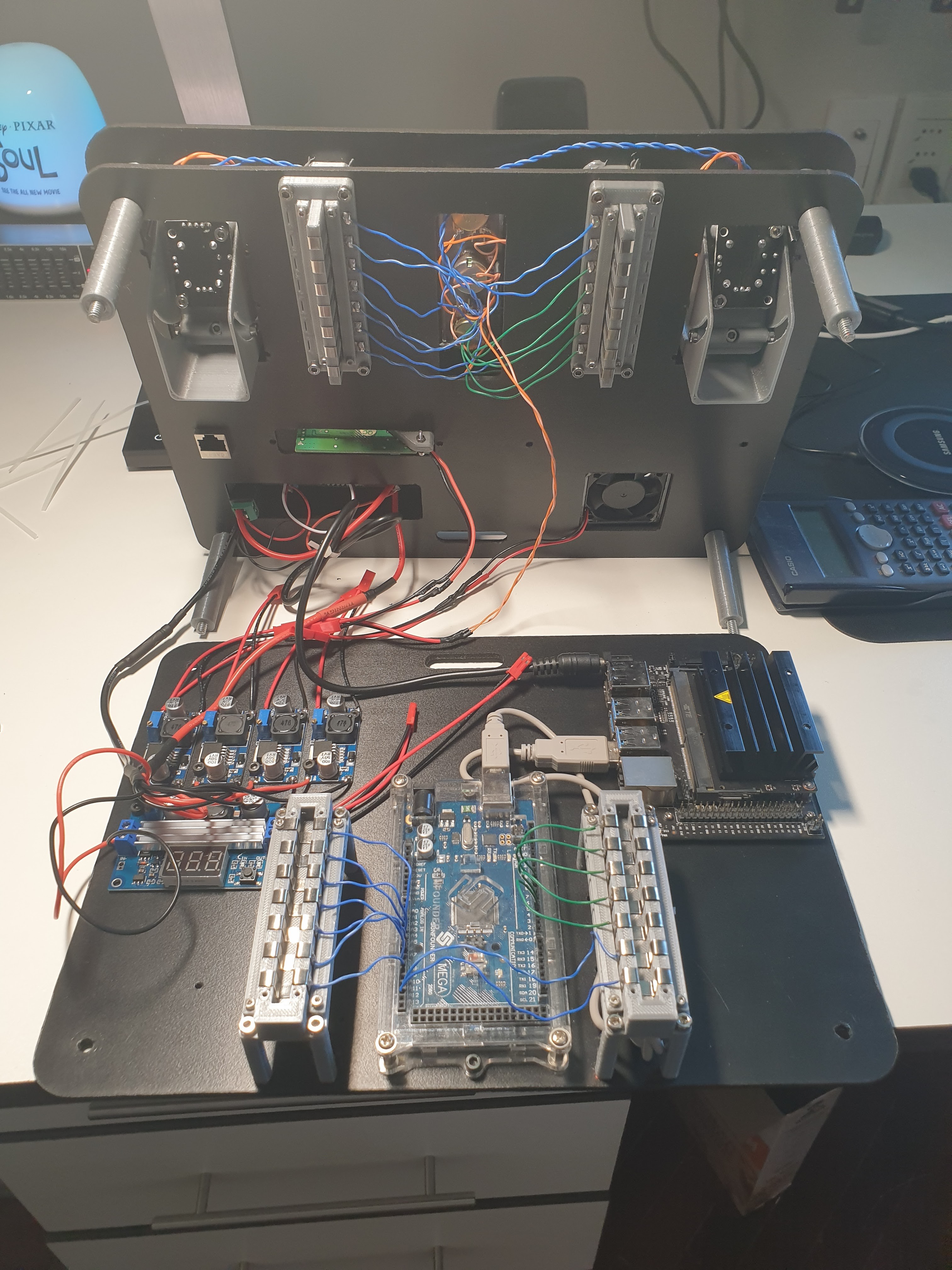
The first step towards building this project was 3d printing the parts at home. I used grey and yellow PLA, with a nozzle of 0.4 mm and layer height of 0.2 mm. The first bunch I printed and assembled looked like this. The RJ45 port is a female-female RJ45 connector which I would connect with a short cable to the Jetson Nano port. The USB hub is an old one I had lying around, I stripped its enclosure, the DC jack connector, and soldered power cables directly to it.
I printed more parts but haven't got any pictures.
The panels were going to be made out of 3mm MDF wood, and would be cut at my school with the CNC cutter. Due to several reasons I couldn't do it at school, but because of the recent completion of another one of my projects, a CNC laser engraver, I could cut the panels at home. Ended up using 3 mm black PVC boards.
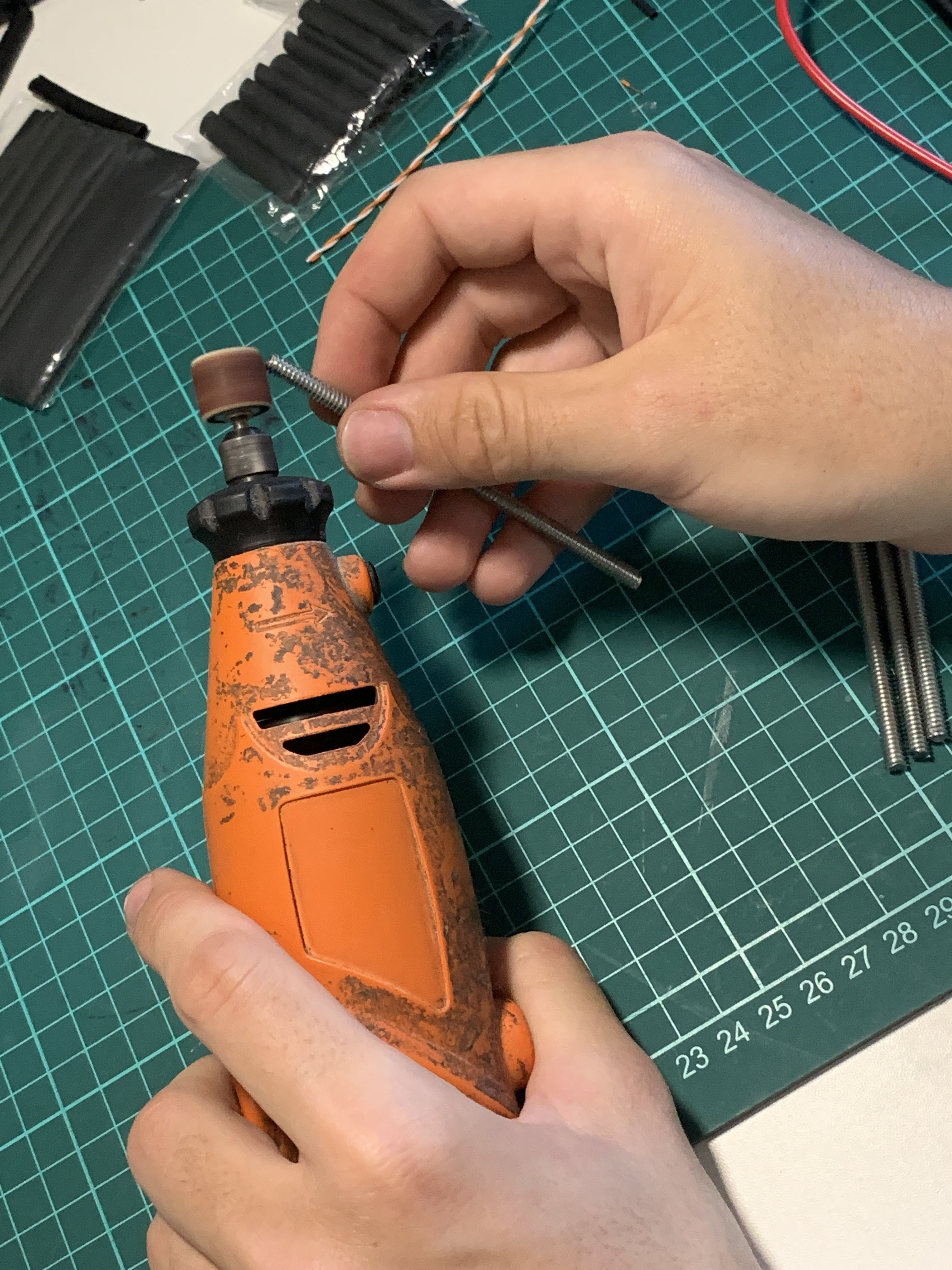
At first, I made each panel in two pieces as the size of the laser engraver wasn't enough to cut a whole panel. After the first parts were cut I didn't like the look, so I went to the hardware store, grabbed some 16mm aluminum tubes, and borrowed the GT2 belt from my 3d printer, enlarged the cutter, and cut the panels in one piece.
Assembly
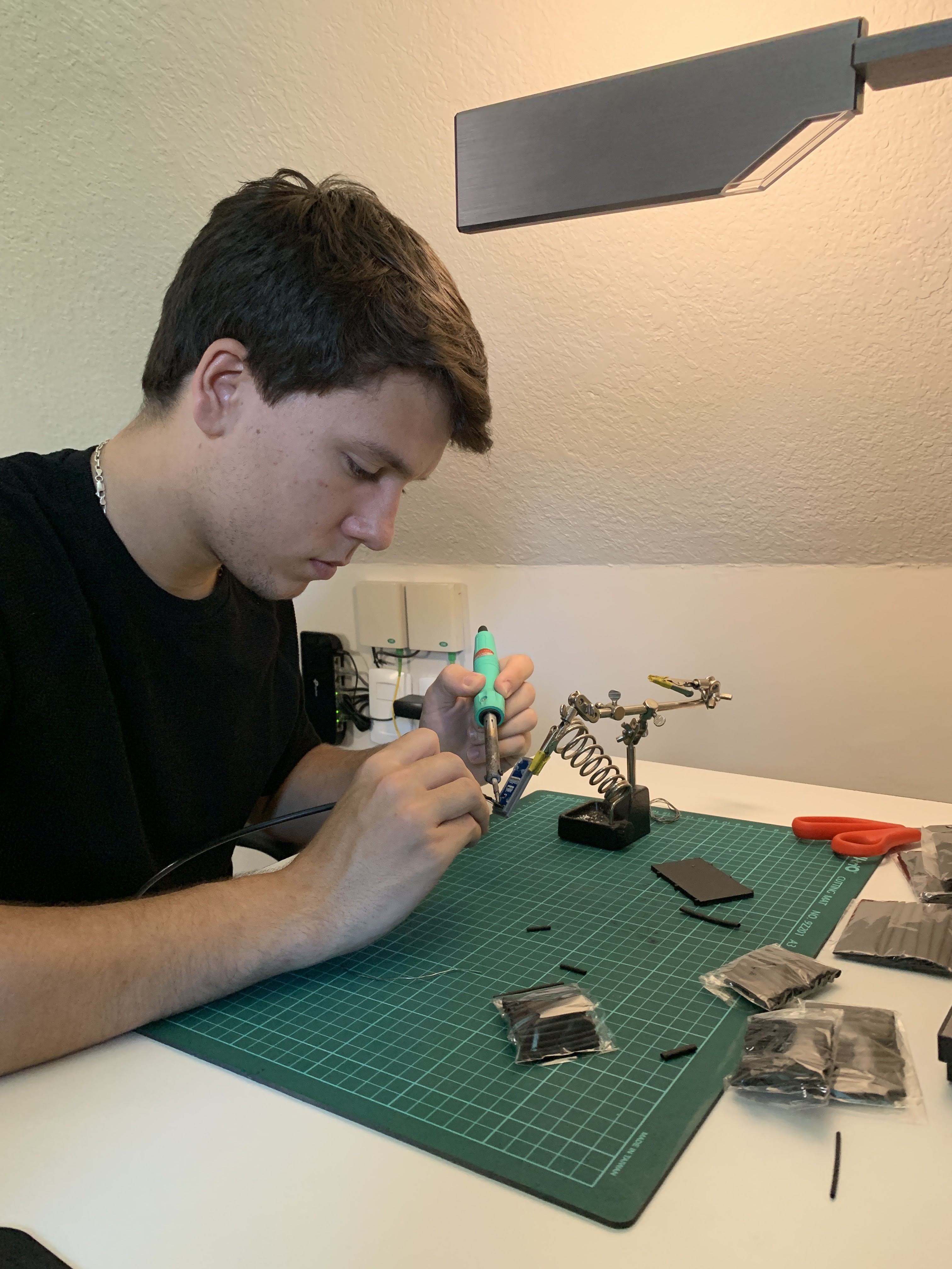
I haven't got pictures of many of the stages in the assembly, but I'll leave what I've got here. It required a lot if screwing (50+ m2, m3 screws), soldering (70+ joints), some epoxy, and a whole lot of cable management. I started with the top panel (the one that goes on the lid) and then proceeded to assemble the ones on the bottom.
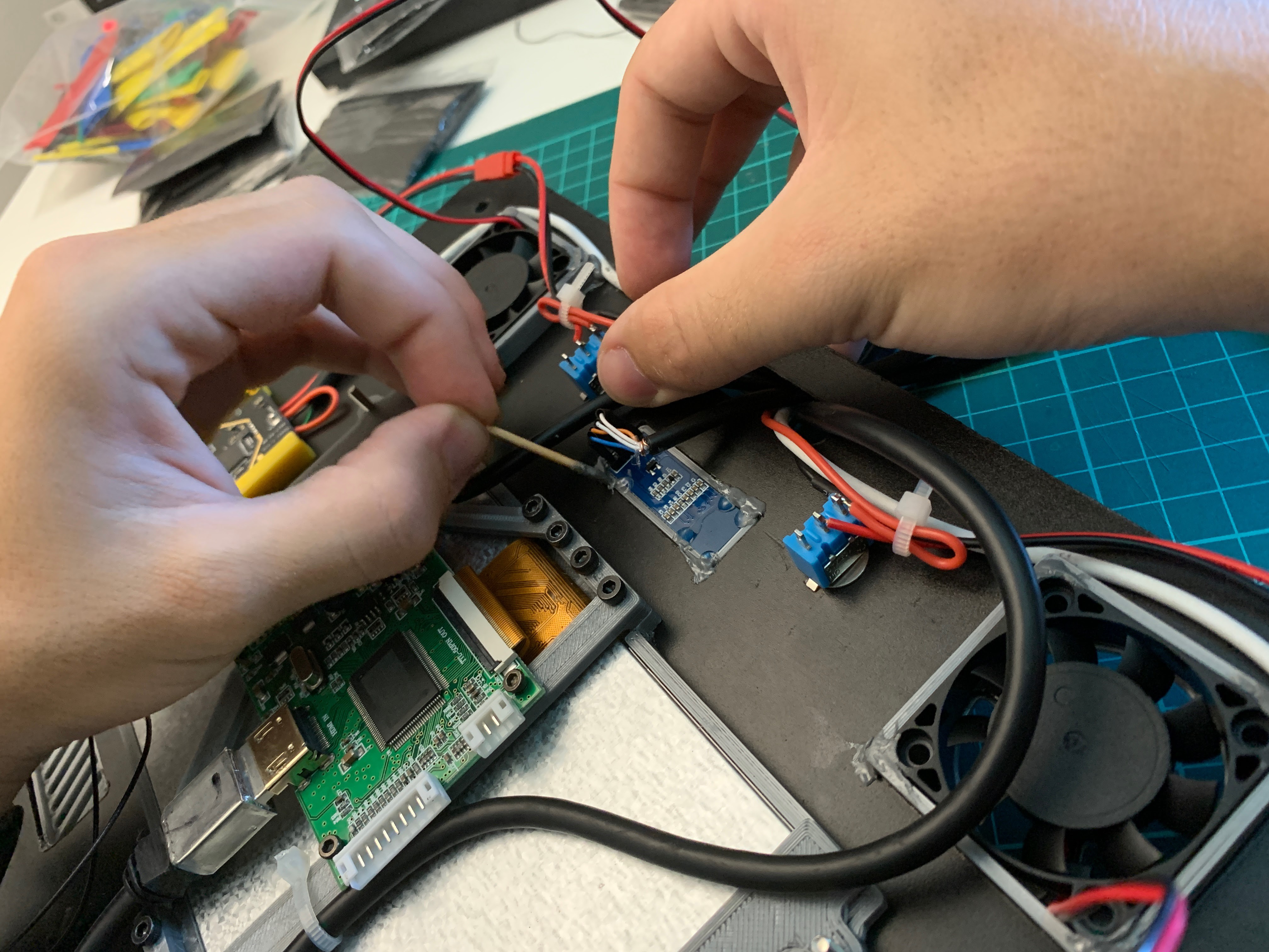
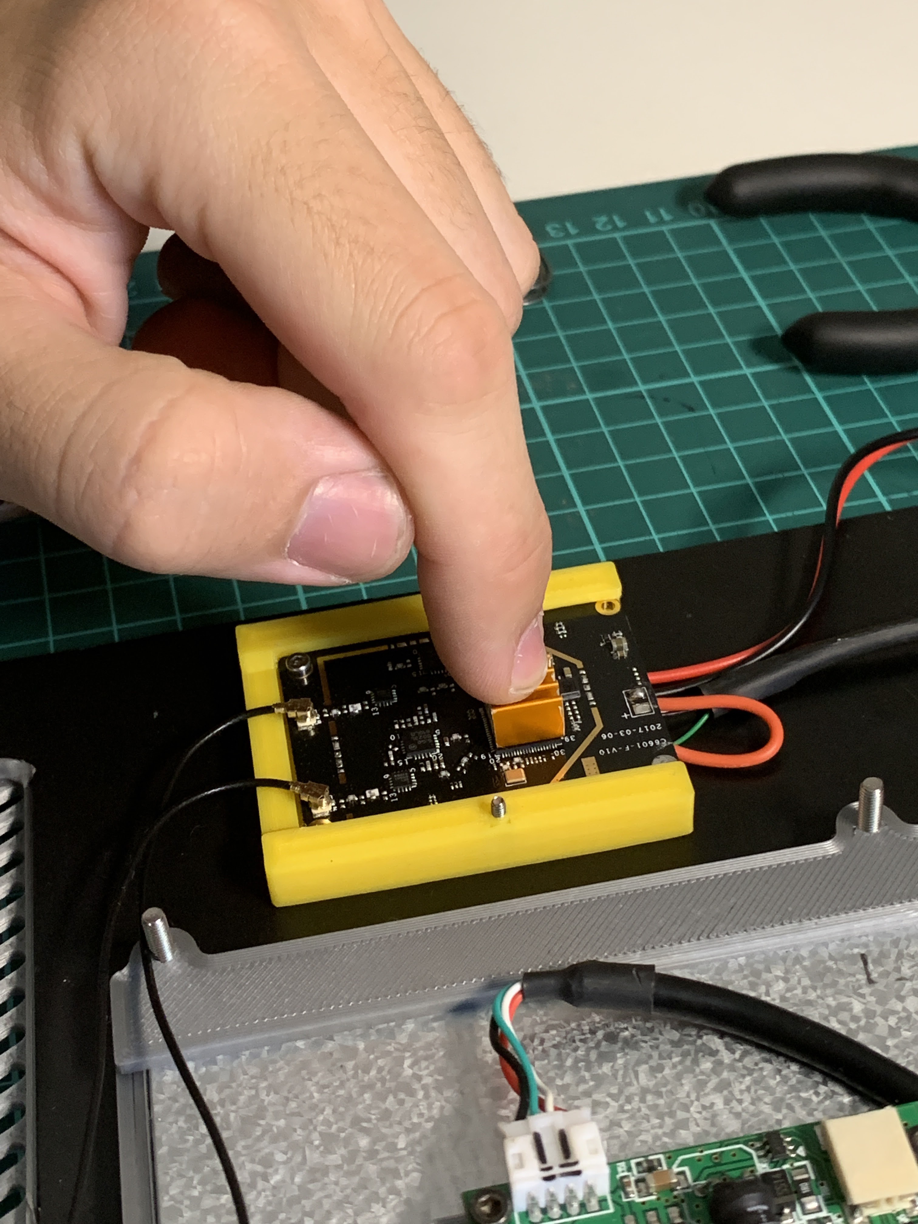
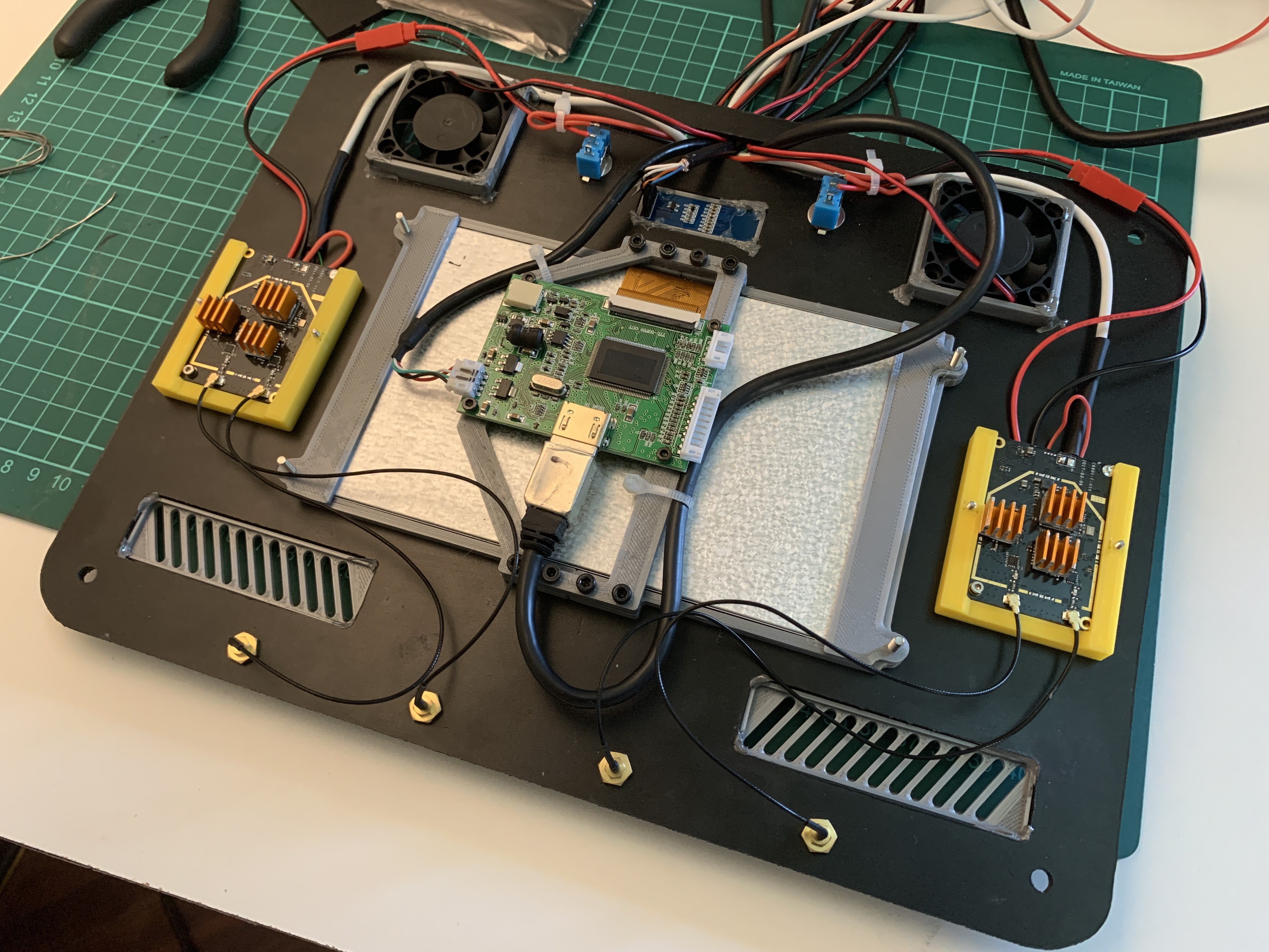
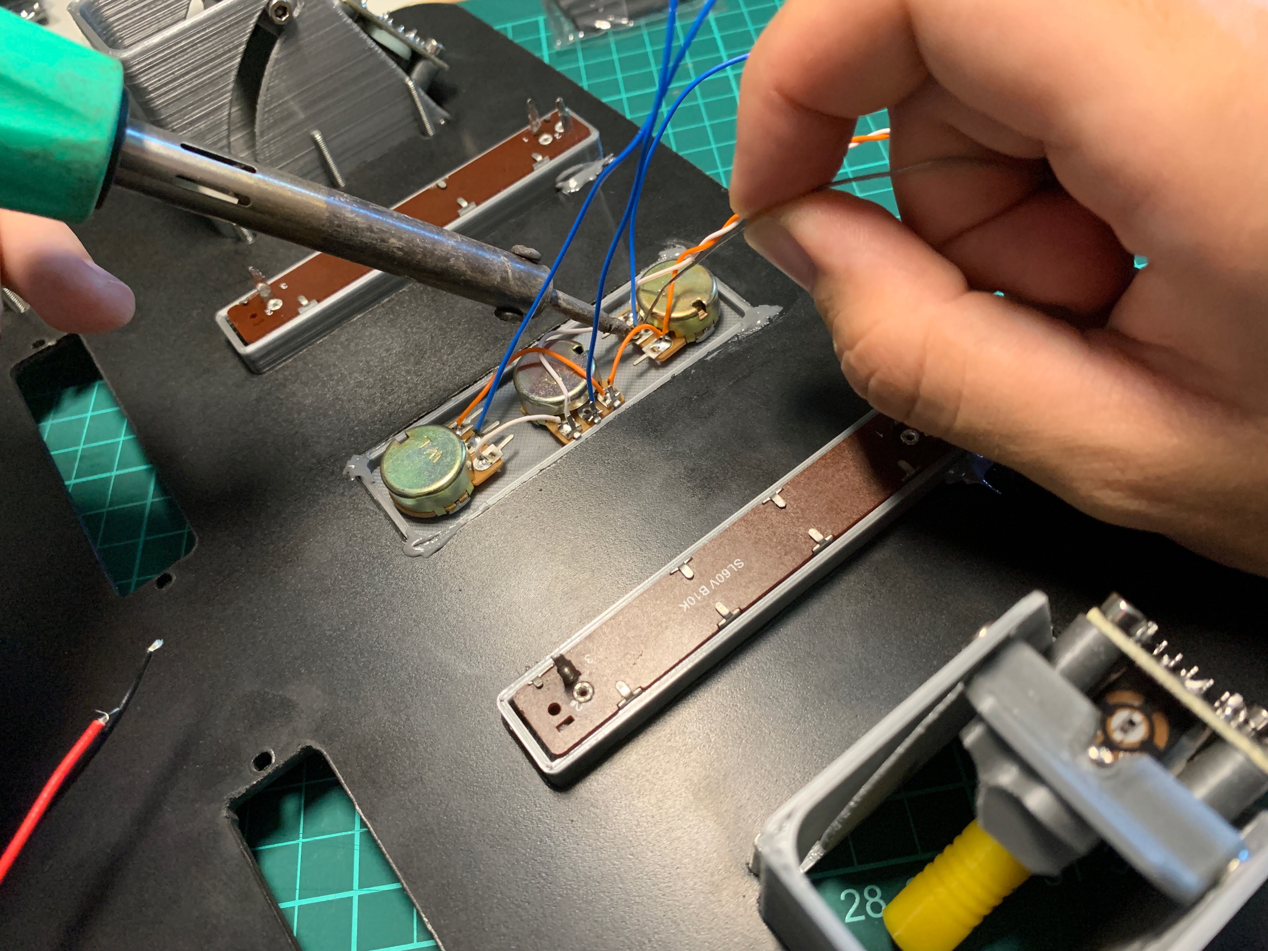
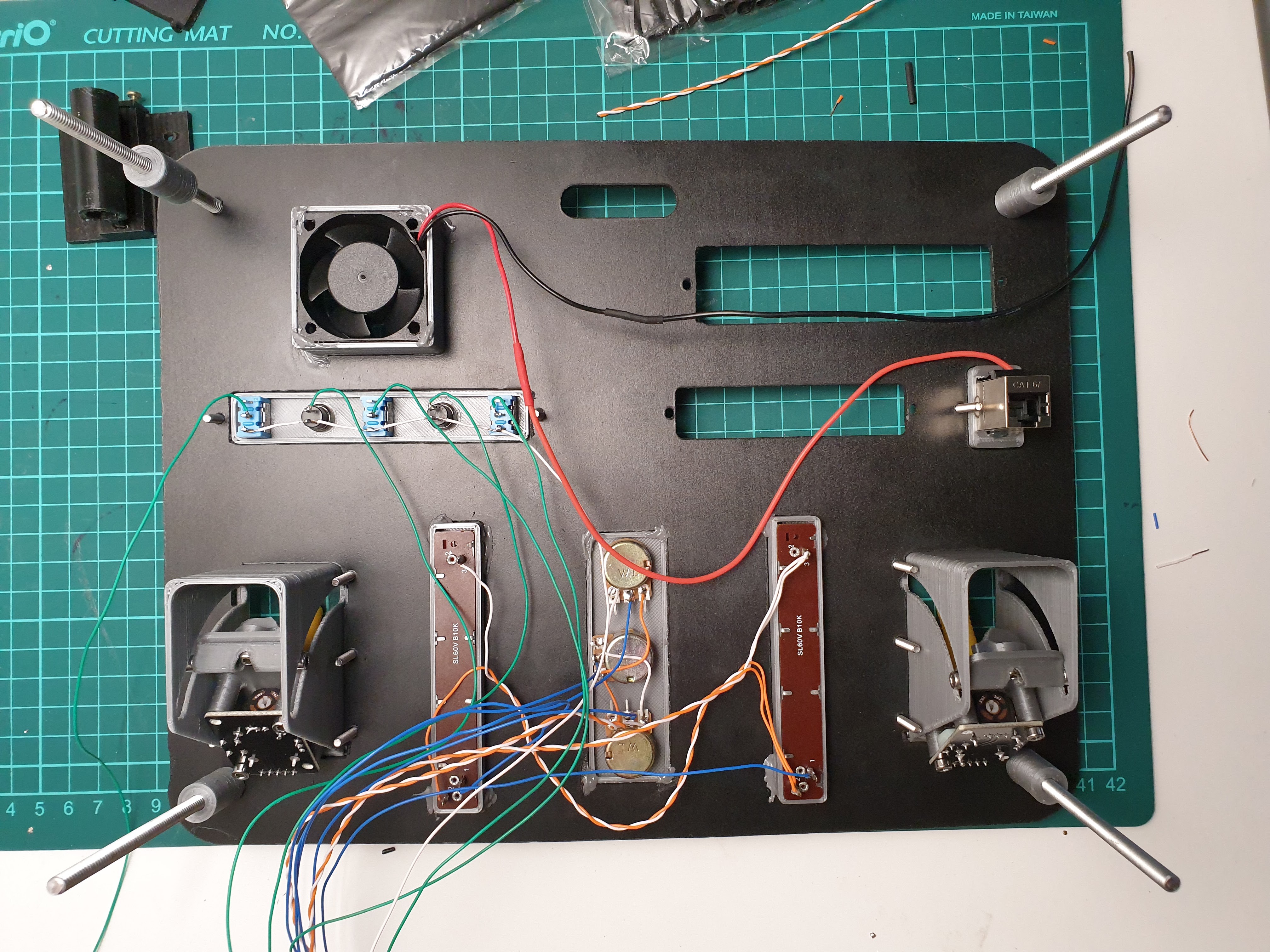
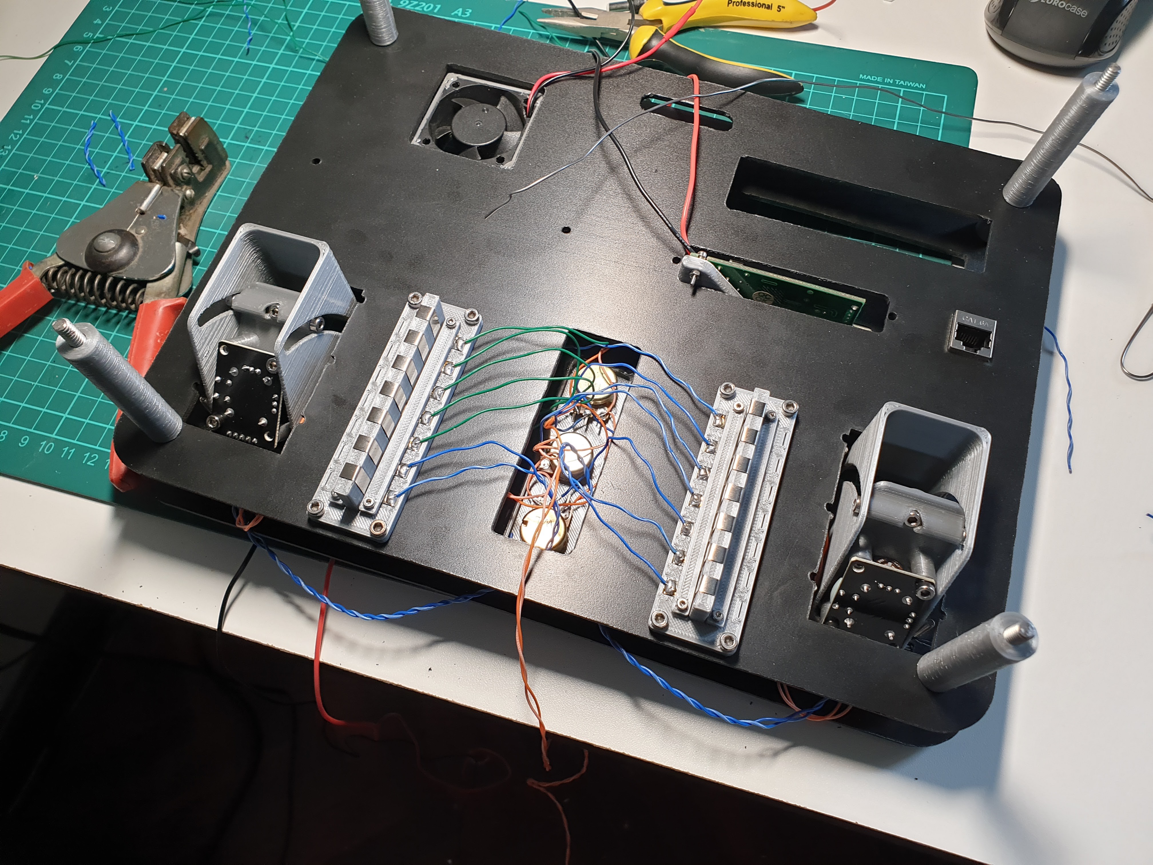
I won't get into much detail because this was a whole project itself, but for increased modularity, better cable management and easier assembly of the whole stack, I designed and made 3d printed connectors that allow for easy connection of the panels. I could have got away with using other existing connector such as pogo pins, or header pins, but liked the idea of experimenting with making my own.
Conclusion & next steps
I'm very pleased with how this project turned out. Some things required a bit of modification along the way, but most things worked as expected.
Until now, I have centered myself in the construction of the GCS. But now it's time to write down some code and make something useful out of it. I'm planning on using ROS (yet need to learn how to use it) and Wifibroadcast for communications, and possibly add some intelligent functions to it, depending on the application/robot. I have already started tinkering with ROS and was able to read the inputs (sticks, pots, switches) from the Nano through a rosserial connection, and transmission of video wirelessly from a Raspberry Pi.
There is space for the addition of inbuilt batteries, so that's on the list of future upgrades.
I have to build something to control now!
PS. I'm migrating some projects from another platform, so some aspects may be incomplete.