I'll post photos of the test setup I have.
Currently I have the 6 address lines set up to dip switches with pulldown resistors. I have each data in pin connected to a button with a pulldown. The chip has an internal resistor I assume is used as a pullup for the open collector output. I've tried the output with the built in resistor and with an external 10k pullup. There is a microswitch connected to the CS pin in the picture to see if enabling and disabling the chip would make any difference but it didn't.
I made an adapter to make connecting the old Soviet designed chips easier. If anyone is interested I can post the files for that.
If anyone comes across this and has any ideas on what I may be doing wrong or knows who to ask about this kind of thing please let me know. If I manage to figure it out I'll update this project and get a tiny memory module made and connect it to an Arduino.
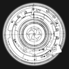
I also delidded one and took a very crappy die shot with my phone camera and the eye piece from one of those kids microscopes. One of these days I'll get one of those USB microscopes. I think it's interesting anyway.
 Tyler Bourne


 SHAOS
SHAOS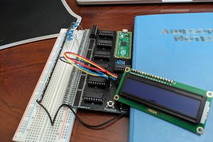
 Mike
Mike
I've got the chip working! First go around was my inexperience with TTL and the second issue was a loose chip select wire. Want to thank hartl and Ken Yap for the advice.
Now I'm going to put 8 of these on a board and make the crappiest memory module! I collect vintage display technology so it will probably end up used in something like that.