 James Dietz
The Challenge
FDM 3D printing is one of the most affordable and accessible ways to start working with rapid prototyping and 3d design/modeling. FDM printers can create a huge number of parts with great utility. FDM printers require little dust collection or ventilation, so they can be used in residential settings, unlike many manufacturing methods.
While the price and quality of printers on the market is steadily improving, there are a number of challenges presented when trying to produce large and/or load bearing parts with FDM printers. As printers stack layer upon layer of molten plastic, the strength of the adhesion between these layers is usually a weak link in a printed part. This means that printed parts are strongest in compression, but in shear or tension can be severed along a part’s layer lines. Furthermore, overhangs can be difficult to print, requiring supports which can be difficult to remove and negatively affect print quality. Finally, the maximum build volume of a printer (with the exception of “infinite-z” printers, which present their own unique challenges) caps the largest size a printed part can be. All of these challenges make it difficult to use FDM to create large load bearing structures.
My Approach
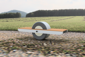
Using electric transportation as a benchmark, the RepRaTS project seeks to expand the types of objects that can be considered “printable”. Tensioned threaded rods connecting a series of printed plastic spacers create the structure of the RepRaTS scooter prototype. This accomplishes two things: first, the tension in the threaded rods gives the scooter its strength and rigidity, and second, the rods force the printed parts into compression to compensate for weakness between layer lines.
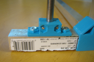
The spacers used in the RepRaTS scooter have mounting holes that are printed perpendicularly to the body of the spacer and glued in after printing. This allows high tension fastening both longitudinally along the beams and laterally across them. As a result, it is relatively easy to mount components to the printed frame in any direction or orientation. This is demonstrated by the scooter prototype, which has to accommodate many parts with arbitrary sizes and mounting patterns/orientations. The battery, motor controller, throttle, brake, hub motors, and handlebar all need to be mounted to the plastic frame and accommodate large loads often in multiple directions.
The second prototype uses very large (13” tire) hub motors to demonstrate an upper limit of the design. If a scooter can be designed to use such large and powerful (1000W) motors, then a designer can comfortably build a smaller vehicle.
The third prototype is designed to be practical for daily use, therefore the motor size has been reduced to 350W 8" hub motors. This greatly reduces the overall weight of the scooter and allows for much simpler packaging of the electronics.
The goal of the RepRaTS prototype is to serve as a demonstration of what types of structures can be produced with FDM rather than as an end goal. Using the same technique, one can make other vehicles, furniture, storage, or many other modular load bearing structures.
I am continuing to design and iterate on the RepRaTS scooter and have a number of improvements in the pipeline, namely splash and impact resistant housing for the battery and electronics, a stiffer and stronger headset connection, end caps for the threaded rods, and an integrated lighting system.
McMaster-Carr parts in the OnShape assembly must be used in accordance with their terms and conditions, available here: https://www.mcmaster.com/termsandconditions/
Quick demonstration video:
 Matt
Matt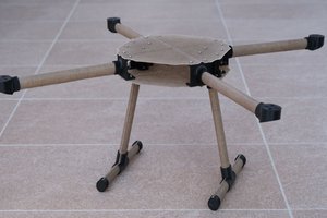
 Mitja Breznik
 Bram Peirs @ FW2W