 Sergio Ghirardelli
-
1Step 1 - Purchase the hardware components
Green BMS hardware components are:
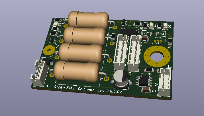
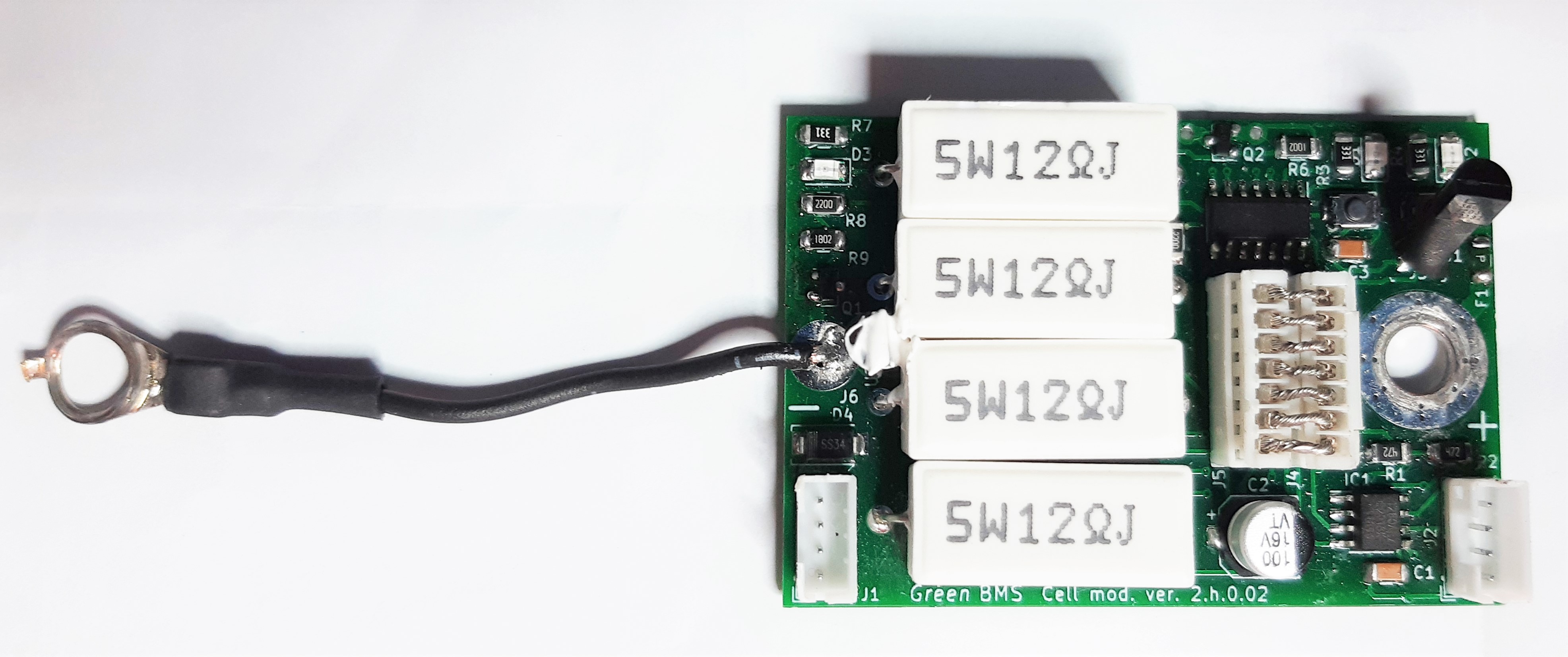
- Cell modules (the quantity is according to cells number) (*)
![]()
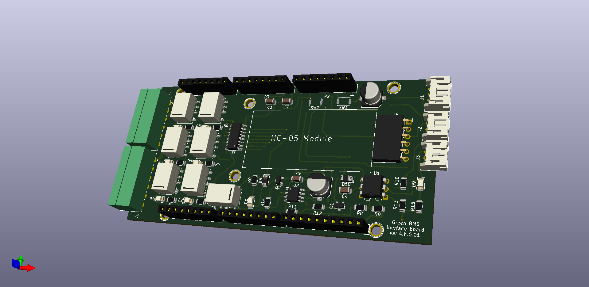
- n.1 Interface board(*)
![]()
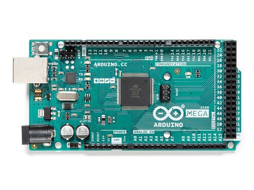
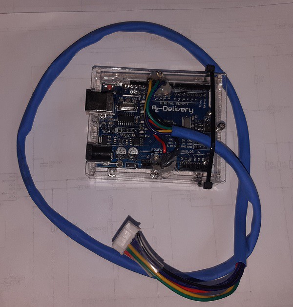
- n.1 Arduino Mega board
![]()
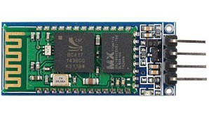
- n.1 HC-05 Bluetooth module
![]()
- n.1 Transparent Plexiglass Control Unit case (laser cut dxf)
- Jst 2.0 PH 7 pins connectors (example to buy)
- Jst 2.0 PH 4 pins connectors (example to buy)
- Jst 2.0 PH 3 pins connectors (example to buy)
- Jst 2.0 female pins (example to buy)
Power charge enable components:
If you decide to use Limiter to manage charge enable and current limiter , you have to buy the components included in this diagram, this is the list:
- n.2 Led diodes
- n.2 1 Kohm 1/4 w resistors
- n.1 510 ohm 1/4 w resistor
- n.1 0,68 ohm 5 w power resistor
- n.1 5k potentiometer
- n.2 diodes 1N4007
- n.2 power relays, coil: 12vdc, max coil current: 1A, 1 NC/NO contact, max contact current: 40A
- n.1 isolated DC-DC 12v-12v converter: Traco TBA 1-1212E
- n.1 NPN transistor BD139
- n.1 N-channel Mosfet IRFZ44N
- n.1 4A fuse
- n.1Thermal switch: Honeywell 2455R 82-195 L70C
- n.1 3p signal connector (min. 1A)
- n.1 2p power connector (min.40A)
- n.1 Heatsink case (this is an example to buy)
As alternative, you can decide to use the charge enable relay you prefere, considering that:
- The coil must be 12vdc, max coil current: 1A
- The NO contact must support the charging current you need
Power discharge enable components:
- Power relay, coil: 12vdc, max coil current: 1A, NO contact, max contact current according to max discharge current
(*) You can decide to assemble PCB yourself. In this case you can order only the PCB and you can purchase all the electronic components according to BOM file available on PCBway store.
-
2Step 2 - Purchase the hardware tools
Hardware tools necessary to make Green BMS are:
- n.1 Arduino Uno board. You need it do load software on Cell Module Attiny84 microcontroller
![]()
- n.1 programming cable, according to this diagram
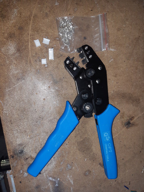
- n.1 Jst 2.0 PH crimping tool (example to buy)
![]()
-
3Step 3 - Install the software tools
To make a Green BMS system, you have to install the following Open Source Applications:
- Arduino IDE (download page)
![]()
- Libre CAD 2d (download page)
![]()
To perform hardware modifications on project, you need the following Open Source Applications:
- Kicad (download page)
![]()
- QElectroTech (download page)
![]()
To perform modifications on Green BMS Android App, you have to use the web open source application:
![]()
-
4Step 4 - Install Green BMS Android App
Install GreenBMS App on your Android device (smartphone or tablet).
![]()
-
5Step 5 - Cell Modules sofware installation
![]()
Install the software on each cell module, performing the following operations:
- Set Arduino IDE to program Attiny Microcontroller (one time operation).
- Add Tinywires Library on Arduino IDE (one time operation)
- Install the software on each cell module
-
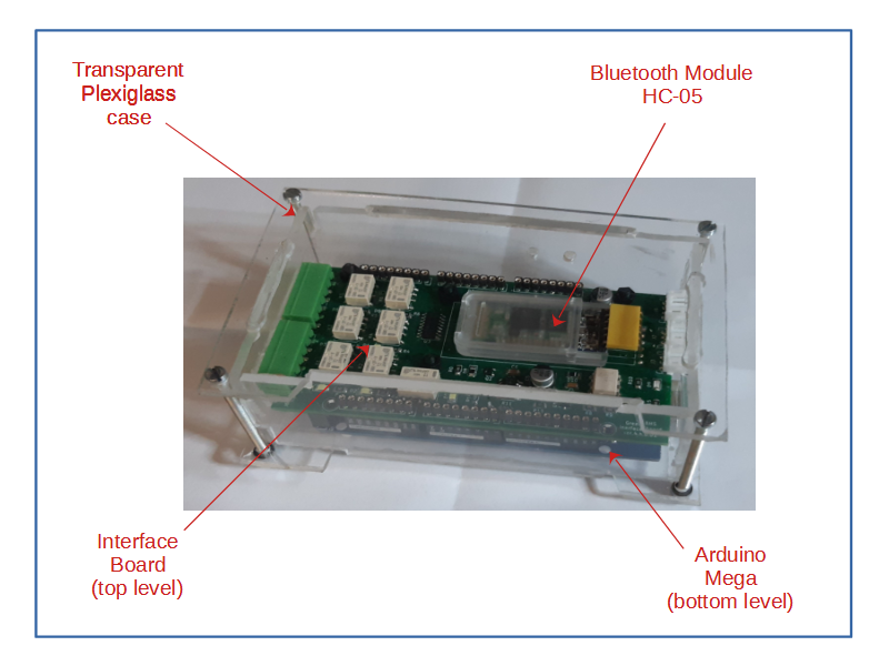
6Step 6 - Control Unit installation
Operate as follow:
-
Install
HC-05 module on Interface board J4 connector (I suggest you to apply
a layer of double-sided adhesive between the module and the pcb)
![]()
- Insert Interface board on top of Arduino mega board
- Apply Control Unit Case. Important: to fix boards to bottom part of the case, use plastic screws and nuts
![]()
Install the software on control Unit, performing the following steps:
- Download the project files from Github repository (go to code/Download.zip)
- Open Arduino IDE and load the last version of Control Unit software (03_Control Unit\Software\Control_Unit_x_y)
- Set Arduino Mega board (Tools/Arduino AVR boards/Arduino Mega or Mega 2560)
- Set ATmega 2560 processor (Tools/processor ATmega 2560)
- Set Programmer AVRISP mkll (Tools/programmer/AVRISP mkll)
- Connect USB cable to Control Unit Mega USB port
- Set USB port where Mega board is physically connected (Tool/port)
- Load the software (Sketch/Load)
- Check that D9 led flashlights: it means that Control Unit is OK!
-
Install
HC-05 module on Interface board J4 connector (I suggest you to apply
a layer of double-sided adhesive between the module and the pcb)
-
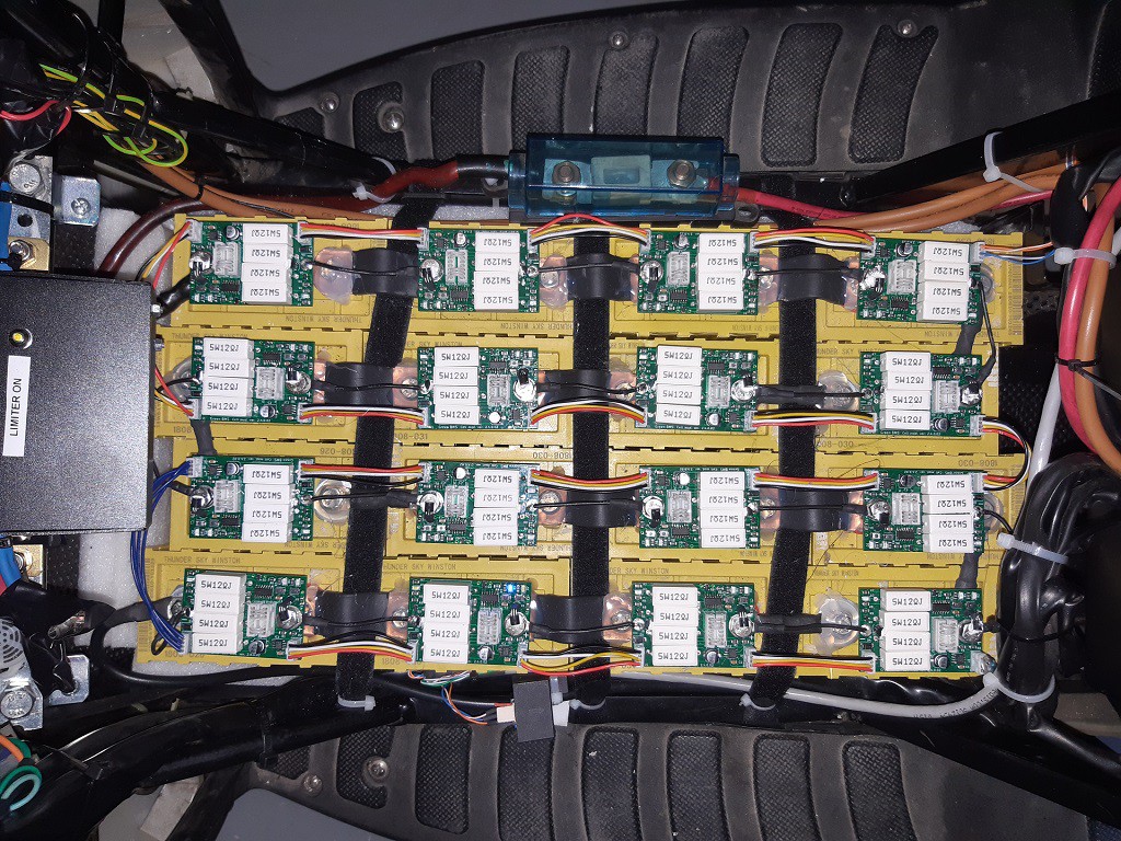
7Step 7 - BMS installation and connections
Perform BMS installations on your battery cells.
Here you can find an exampleof installation on a 16s 48V battery pack
Reccomended steps:
-
Solder
negative wire with eyelet terminal to each cell module.
![]()
- Connect Cell Module on each battery, without J4-J5 7pins connectors (to cut module supply)
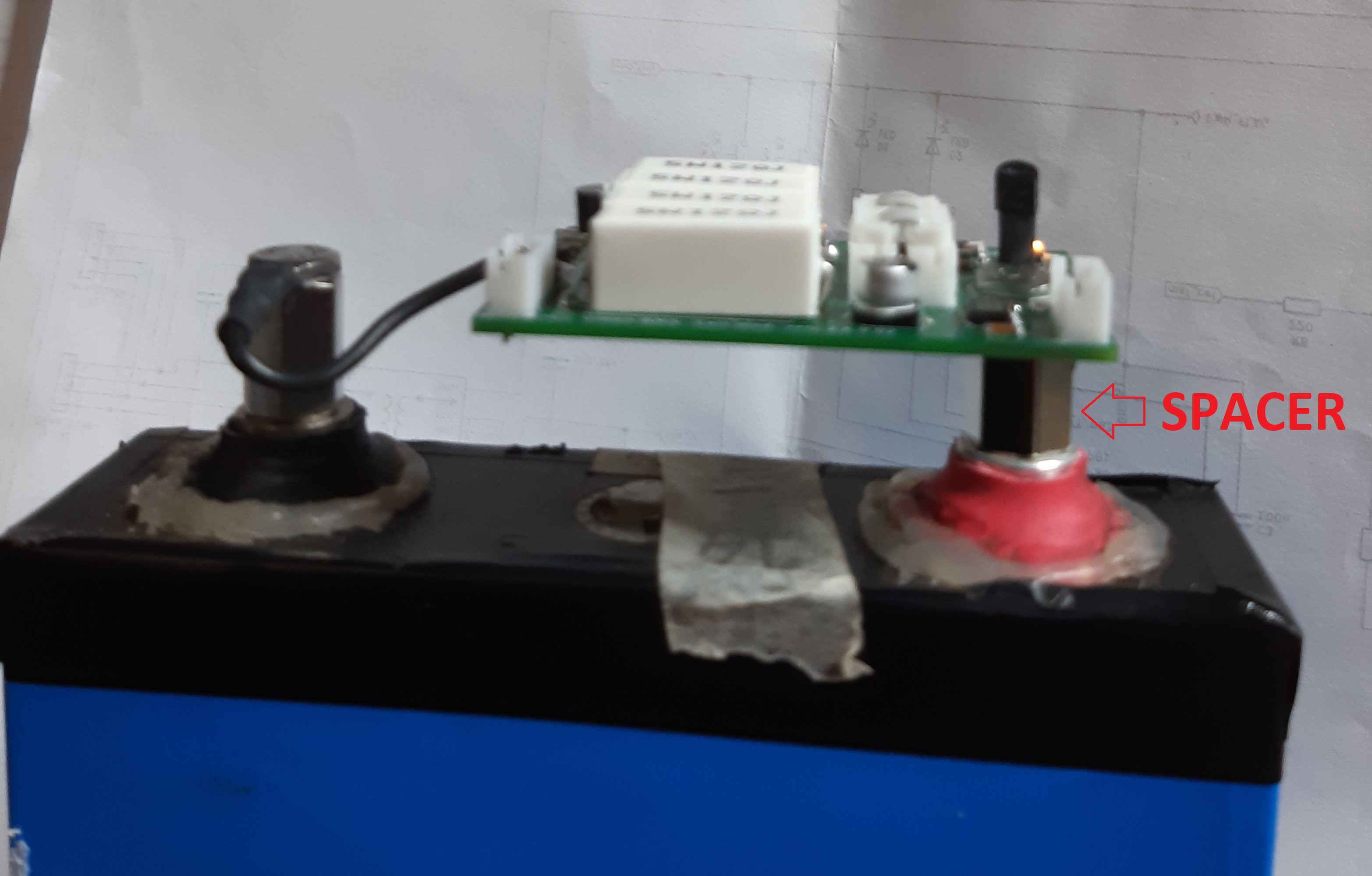
-
Important:
don't connect power battery cables above the cell module: high
currents must not pass through the positive hole of the module. I
recommend the use of male-female spacers (here is an example of purchase)
as in the attached photo, this solution consents to separate power
cables from cell modules: you can for replace a cell module without
disconnect the power cables!
![]()
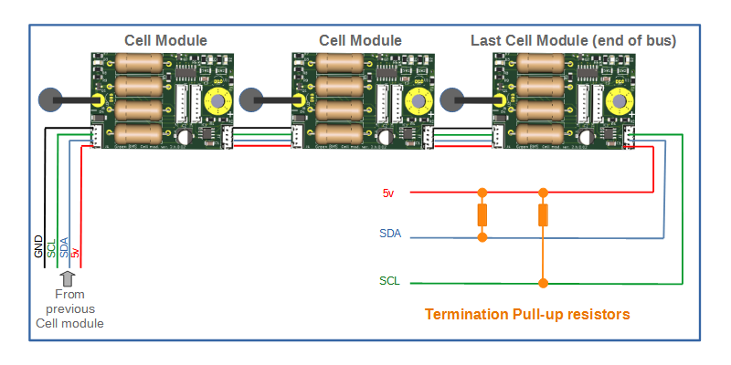
- Connect i2C bus cables (4 wires pin to pin Jst connectors) between each cell module and between first cell and Control Unit
-
Important:
on last cell module of I2c bus (the one that have one connector
available) it can be necessary to plug a termination connector with
calibrated pull-up resistors (see picture): I reccomend to use
resistor values that bring the total pull-up resistor of the bus =
1,5 Kohm.
![]()
- Connect current sensor (use sensor with 5v supply) on J2 3p connector
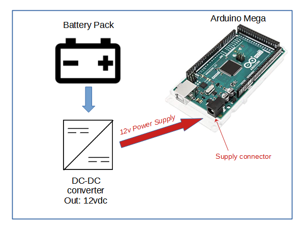
-
Connect
other signals (Control Unit 12vdc power supply, outputs, alarm led,
etc...)
![]()
- Plug J4-J5 7pins connectors on each module.
![]()
-
Solder
negative wire with eyelet terminal to each cell module.
-
8Step 8 - Connect with Android App
Operate as follow:
- Enable Bluetooth on Android device settings
- Start Green BMS app from android device
- Click
on "Connect to device"
![]()
- Select the HC-05 Bluetooth connection on list
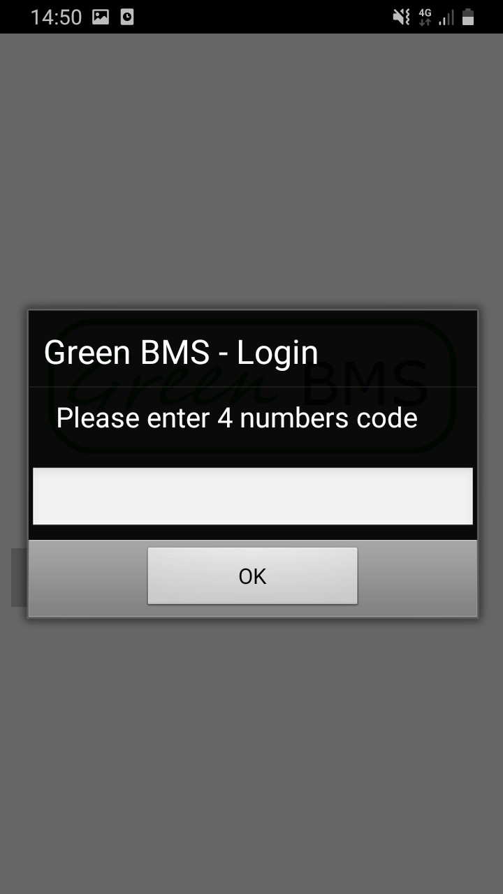
-
Set
the starting 4-digit password number: "1234"
![]()
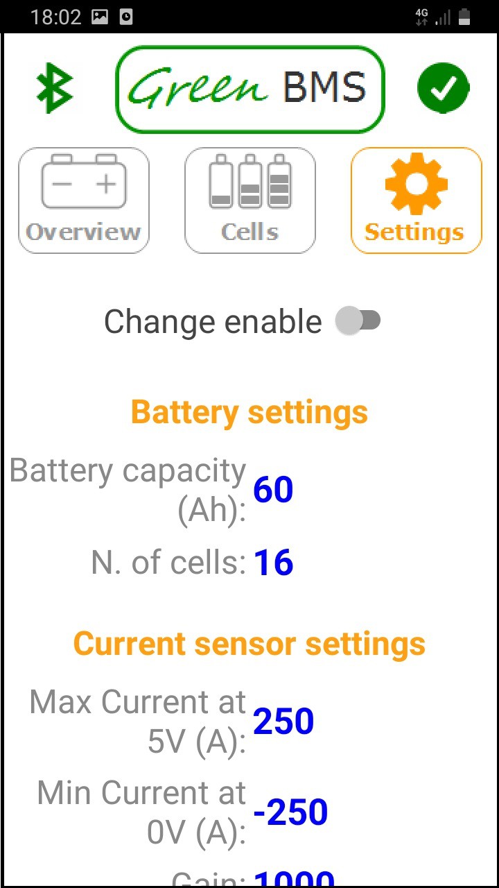
-
Open
"Settings" page and set the default parameters value for
your system (the meaning of each single parameter is described
on this page)
![]()
- It is recommended to change the 4-digit password
-
9Step 9 - Set Cell Modules Address
-
10Step 10 - Perform Cell voltage calibration


Discussions
Become a Hackaday.io Member
Create an account to leave a comment. Already have an account? Log In.