Stephen Moody
-
Another FPGA video card update
04/06/2024 at 13:54 • 0 commentsI’ve been working on adding some new features to my VGA video card.
The initial FPGA code for the VGA card was very much done as a proof of concept, learning how to generate VGA signals, using the SRAM as a framebuffer and interfacing with the 68000. It was a learning experience in the VGA card design and expanding my knowledge of VHDL.The previous version of the card was working well and it had a 80x30 text mode and a 640x480 12-bit (4096) bitmap mode along with some hardware accelerated drawing functions.
The text mode was working but has been updated as previously, while the text colour could be changed, it was limited to changing the colour of all text on screen. Now each character has its own foreground and background attributes. It’s limited to 16 colours each for the foreground and background from a fixed palette.
While having a 640x480 bitmap mode was nice but updating bitmap graphics at a reasonable speed on a 10Mhz CPU is not going to be practical so the plan has always been to have a lower resolution “game” mode of 320x240 with a 12, 8 or 4-bit palette that supports tile based graphics and sprites in addition to the bitmap display. This update implements the 320x240 bitmap mode and also includes an 8-bpp palette. Both bitmap modes can use the full 12-bit colour or the palette for display.
The initial implementation of the 320x240 mode was reasonably straight forward as it’s just adjusting the address in SRAM where it was fetching data. There is no caching of the data so currently the same data is being fetched from the RAM framebuffer more than once in the 8-bpp and the lower resolution modes. This is fine for just displaying bitmap data as it currently is, but this will need to be changed to add some of the planned features.
Once the different bitmap modes were working, the next feature I wanted to add was hardware scrolling. In theory this is an easy solution, just calculate the address in memory for the bitmap data you want to display. For resolutions of 640 and 320, they translate into fairly simple math for the FPGA to calculate the address for the next row of data. The initial idea was to have bitmaps of arbitrary sizes.
In practice having an arbitrary sized bitmap caused some speed issues in my implementation so as a compromise for that, using fixed width modes in a similar fashion to how the V9990 handle things solves the math issues. Bitmap widths can now be 512, 1024, 2048 or 4096 pixels wide. As the VGA card only has 2MB of video RAM, it limits what is available in different video modes. Vertical height is limited by the bitmap width and the available video memory. Fixing the bitmap width simplifies the scroll logic and scrolling past the bitmap width just results in the image wrapping around.
For the palette, it allows a selection of 256 colours out of a possible 4096. Currently only one palette is used but there a total of 4 separate palettes is supported. The plan eventually is to be able to have different palettes for bitmaps, tiles and sprites.
Overall I’m happy with the progress made but there are some limitations on the new video modes. The hardware drawing functions that I had previously implemented will only work on the 12bpp modes.
The next stage is to add caching of pixel data to make memory access more efficient. Once that is done, the next stage is to implement a tiled bitmap mode.
-
FPGA VGA Card V2
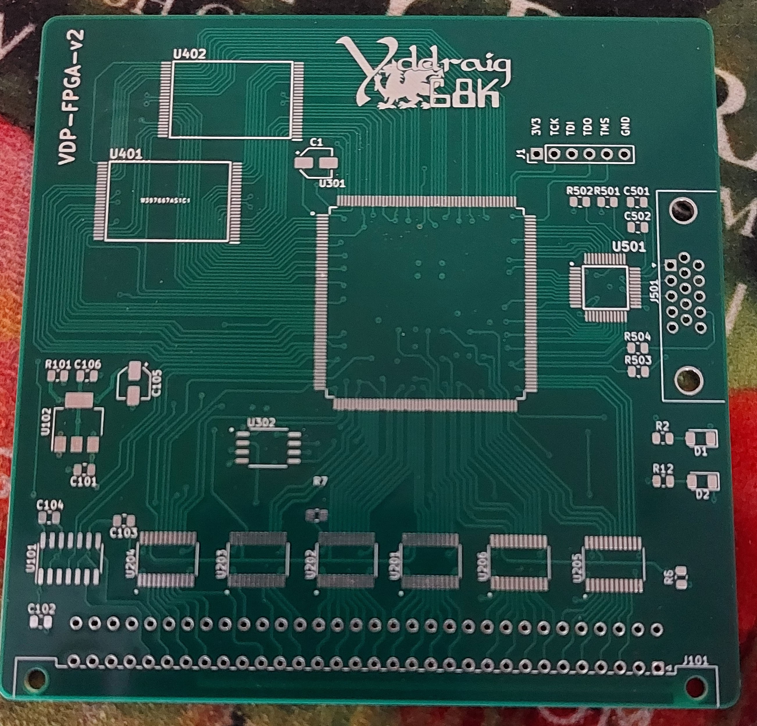
02/21/2023 at 16:55 • 0 commentsWhile I already have a VGA card that I built previously, I have started working on a new version as well. Part of the reason for the new board was to increase the number of colors displayed. The old version used 12-bit color (4,4,4) to have 4096 colors in total. The new board has full 24-bit color using a ADV7123 Video DAC.
The last board used a Xilinx Spartan 6 XC6SLX9 which was the largest QFP package in that range, this board uses a Xilinx Spartan 3 XC3S500E 208 pin QFP package. In addition to the improved colour output, the SRAM was doubled to 4MB in a 1Mx32-bit VRAM which should provide a lot better bandwidth.
![]()
I designed the board last year and back in August the board was sponsored by PCBWay who kindly made some for me. The boards are good quality and well made.
At the moment the project is on hold as the last 6 months have been crazy busy and I didn't have much time for personal projects. It's only recently I've had some time to start back working on some of these hobby projects.
The main reason I'm posting this now is that I've been getting constant emails from PCBWay asking to promote them and today hit a breaking point where I had an email which was just straight out rude and pushy so here's my review.
The actual PCB is nice but if you have something built by them for free, expect a lot of badgering until you give them what they want. I won't be ordering anything from them in the future after this and I can see any benefit of the service they offer over other places.
-
V9958 and V9990 Video cards
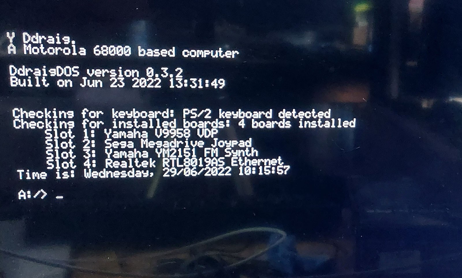
07/04/2022 at 12:51 • 0 commentsYamaha V9958 Video Display Processor
The Yamaha V9958 is the successor to the V9938 and TMS9918 that were commonly used in the MSX computer line with the V9958 appearing in the MSX2+.It has the following specifications:
- VRAM: 128 KB + 64 KB of expanded VRAM
- Text modes: 80 x 24 and 32 x 24
- Resolution: 512 x 212 (16 colors out of 512) and 256 x 212 (19268 colors)
- Sprites: 32, 16 colors, max 8 per horizontal line
- Hardware acceleration for copy, line, fill, etc.
- Interlacing to double vertical resolution
- Horizontal and vertical scroll registers
The board has 3 different outputs. A composite output, S-Video output and a Xrgb Mini RGB compatible 8-pin mini DIN output aimed at SCART use. There is also an optional audio jack input that can supply audio the 8-pin din output so TV speakers can be used rather than an external speaker.
The V9958 board has 192K of RAM installed and uses a CXA2075M encoder to provide the video output signals.
This board was a challenge to get working under the operating system. I wrote several test programs that run under the monitor software to test the different video modes. Both graphics and text modes worked well. Unfortunately, when writing the driver for the OS I just could not get the text mode to display correctly. It was either a mix of some random characters or, more often than not, a black screen. Even though the OS code was mostly based on the code I wrote for the initial tests, it just didn’t seem to work. I eventually wrote some of the access routines for the V9958 in assembly and that did seem to fix the problem and it works reliably in text mode under the OS now.
I suspect that some of the issues that I’ve encountered here are down to timing in accessing the card and writing some of the code in assembler has improved things there. While the code worked well using the monitor software, for the most part there are no interrupts running unlike the OS. I still need to find the root cause of this as if it is a timing issue then as the OS evolves it could come back at some point.
V9958 Text Mode
![]()
V9958 Mode 7 - Mandelbrot
![]()
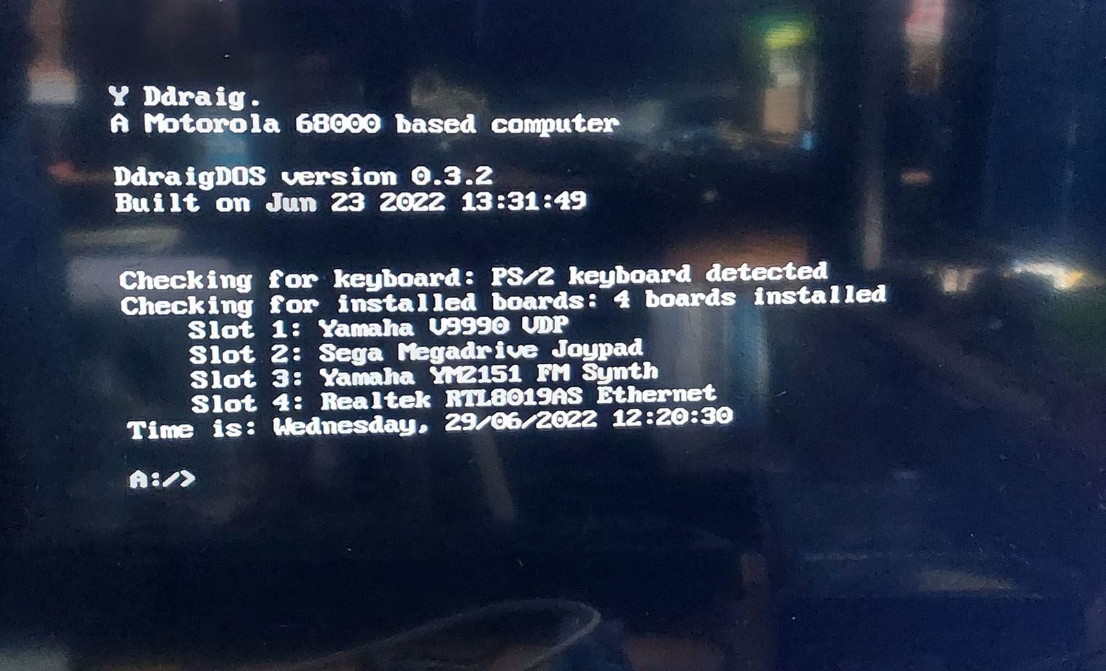
Yamaha V9990 Video Display Processor
The V9990 was intended as a successor to the V9958 (or supposedly a stripped down version of the never finished Yamaha V9978), but while the other chips in the range had backwards compatibility with the previous generation, the V9990 has some similar functionality but lacks the backwards compatibility.
Still, the V9990 has impressive specifications for the time, some of the features include:
Game Specifications:
For this type, there are two pattern display modes.
- P1 (Display resolution 256 x 212 2 screens)
- P2 (Display resolution 512 x 212)
Various highly advanced functions are available such as powerful sprite function and omnidirectional scroll function.
AV Specifications:
For this type, there are four kinds of bitmap display modes which can be displayed on the NTSC or PAL frequency monitor as follows.
- B1 (Display resolution 256 x 212)
- B2 (Display resolution 384 x 240)
- B3 (Display resolution 512 x 212)
- B4 (Display resolution 768 x 240)
Capable of doubling the resolution in the vertical direction by using interlace. Display is possible up to 32,768 colors/dot. Built-in color palette (64 colors selected out of 32,768 colors). Omnidirectional smooth scrolling is possible.
Like the V9958 card, the V9990 has Composite, S-Video and RGB output. The board has 512K of RAM installed and again uses CXA2075M encoder to provide the video output signals.
V9990 Text Mode
![V9990 Text Mode]()
V9990 Pattern mode test
-
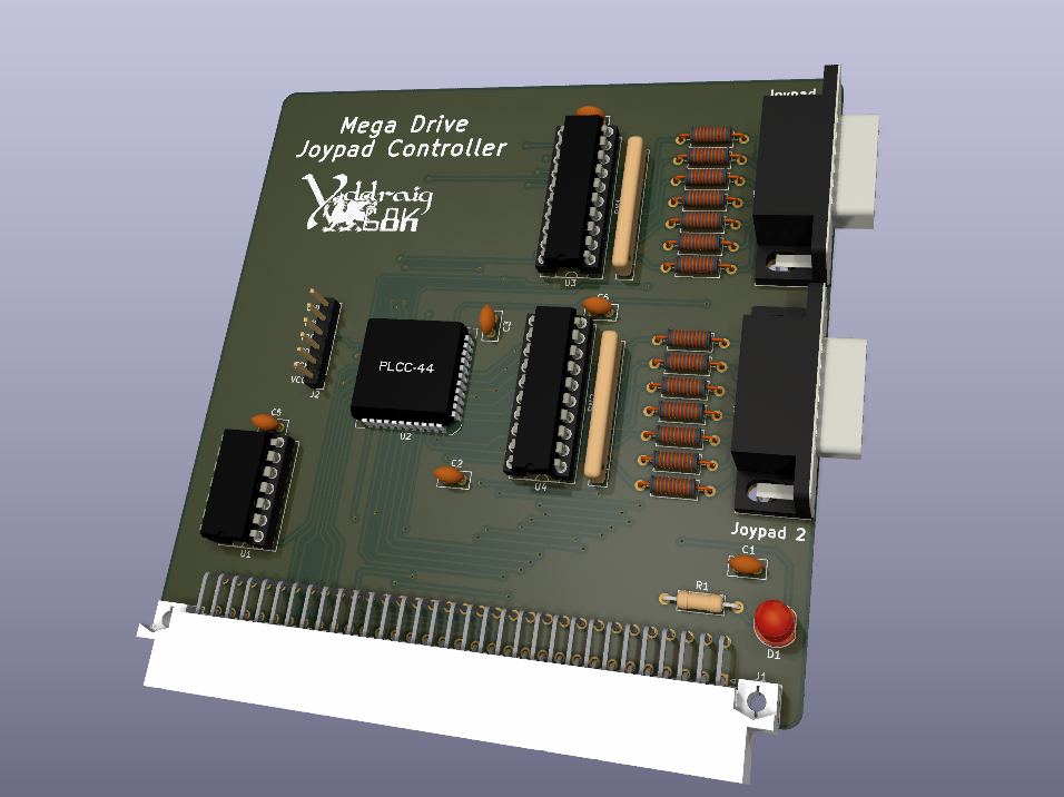
Sega Megadrive (Genesis) Joypad Controller
06/29/2022 at 15:33 • 0 commentsThis board, along with others has taken me some time to get around to testing.
This is the simplest of the expansion cards i've designed for Y Ddraig. It supports 2 controllers and consists of a Xilinx XC9536 CPLD for handling the bus interface and supplying the SELECT lines to the Joypads and 2 latches for reading back data.
Other than few false starts in understanding how the controllers are read, then it works very well. I’ve only tested it so far with the 6-button controllers as they are the only ones I have available but as they are the more complex ones to read, I’m fairly confident that the 3-button controllers will work fine.
![]()
-
A YM2151 Sound Card
12/11/2021 at 14:25 • 0 commentsThis sound card is based around the Yamaha YM2151 8 channel FM synthesiser. It was used in some Yamaha synthesisers and systems such as the Sharp X68000 and many arcade games.
While this is a new board, it was based on a previous design. It was a board designed alongside the earlier revision of Y Ddraig, before switching to the current version in KiCAD.
There has been some changes between the previous and current designs. The layout of the board has been reduced to fit into a 100mm x 100mm design which has allowed me to make it a 4 layer board without incurring a large additional cost. The 4 layer board also allowed better layout of power planes which should help reduce noise on the analogue side.
Instead of using a fixed frequency crystal, I’m now using a LTC6903 programmable oscillator for the clock. While a fixed frequency oscillator would be fine for this, the change allows music from VGMRips player to work a bit more accurately as different systems use different clock speeds.
The previous version of the board was using a XC9536 CPLD for the logic decoding, but it was changed to an XC95144XL in this design to allow a bit more space to add the SPI interface for the clock generator.
Other than some issues with getting the SPI code working correctly on the CPLD and a couple of minor decoding issues, bringing up the board was a relatively painless process. Modifying the VGM music player I had written previously to set the clock frequency was easy enough and it run without any issue.
A small video of a couple of songs playing. Playback speed isn’t 100% accurate on these as I still need to implement a proper timer on the player, but it’s close enough for most things.
-
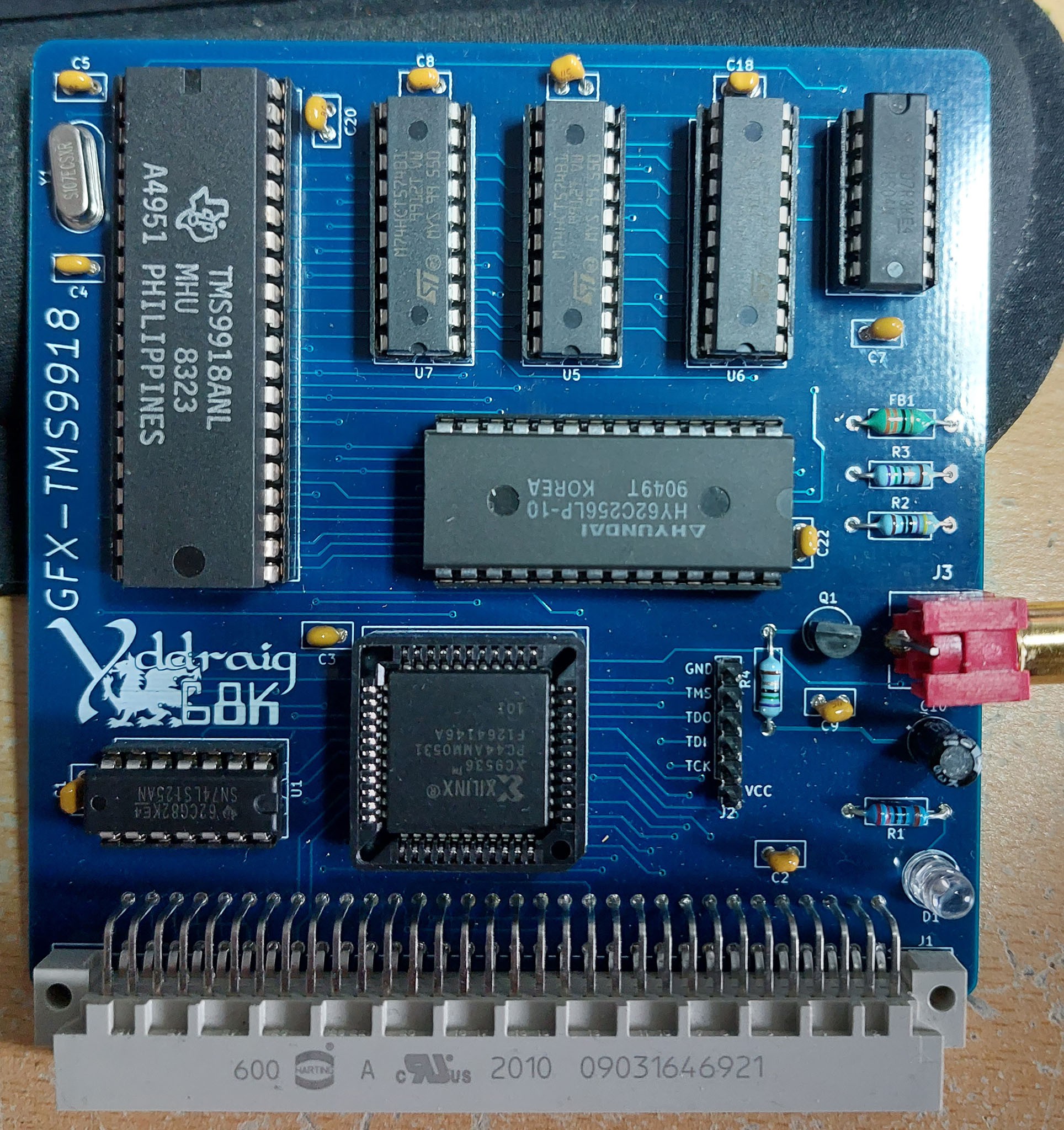
TMS9918A Expansion Card
10/17/2021 at 13:08 • 0 commentsWhen I ordered the new PCB for Y Ddraig, I also ordered some additional expansion card PCBs. A couple of these I had made previously and just moved the design from Proteus to KiCAD and making a few changes to the design. Others were new boards and will be interesting to get up and running.
The boards are a mix of graphics, sound and peripheral devices. There's 3 graphics boards based on the TMS9918A, V9958 and the V9990 chips. Two sound boards based on the YM2151 and the YM2612 and some periperals boards for a floppy disk controller using the WD37C65C, Ethernet using the RTL8019AS and a joystick interface for Sega Megadrive (Genesis for the US) controllers.
One of the reasons I changed Y Ddraig from a single board computer to using expansion slots was to be able to experiment with some of these old chips and this is the first of many that I'm testing.
The first board I chose to start with was the TMS9918 video controller. While it's lacking in capability compared to some newer solutions, I wanted to try something with this chip as it was used in the Colecovision which I had a kid, a console that my brother and I spent many hours playing as kids. It was also used in
I chose to use the TMS9918A for this rather the TMS9929A PAL version as it directly outputs composite directly, and most TVs can handle NTSC these days.The TMS9918A is capable of a 256x192 pixel display with a 15 colour palette. It has 16K of video memory and 4 different video modes.
From the Sega Retro site:
There are 4 different screen modes available in the TMS9918A (as mentioned before, the TMS9918 lacks mode Graphic II):
Mode 0 (Text): 40×24 characters monochrome. As the display is 256 pixels width, the character set is only 6 pixels wide. This mode doesn't support sprites, nor a separate border color setting.
Mode 1 (Graphic 1): 32×24 characters (256×192 bitmap), where for each 8 characters in the character set the foreground and background color can be set. The chars "0"-"7" for example all have the same attributes.
Mode 2 (Graphic 2): 32×24 characters (256×192 bitmap), with a 2-color limitation for each 8 pixel wide line inside a character.
Mode 3 (Multicolor): 64×48 mode, very blocky and rarely used. Each 'pixel' can have its own color defined though, hence the name. Its sprites still have the same resolution as in screen modes 1 and 2.
The TMS9918 has a fixed 16-color palette (actually 15 colors + transparent).
The TMS9918A was designed to use DRAM, but I have used the design by Leonardo Miliani that allows SRAM to be used instead.Bring up the board went well in some ways but initially I had nothing on the composite output. Mistake on the footprint for the connector meant that the signal and ground were swapped. I made up a simple cable that swapped the signals and i managed to get a signal on the monitor.
I wrote a couple of simple test program just to make sure that the board was working correctly. One to write something to the screen in text mode and a simple test of the graphics mode.
It would be nice to get something better running on the board before I move on to the next one but at this point I can call it a success.
![]()
![]()
![]()
-
Expansion Bus
09/07/2021 at 15:26 • 0 commentsThere are 4 expansion slots on the board.
Each slot is using a 64-pin DIN 41612 connector. The connector supply data, address and some common bus signals as well as power to each of the boards.
There are also 2 select signals for each slot, all access for each slot is memory mapped on on the address bus.
One is a 256-byte range that is designed for register access or control and a 1-Megabyte range for accessing data. For example, on the VGA card the control of the card if done through the registers, but if needed direct access to the VRAM can be done through the data range.
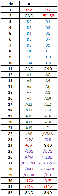
The signals for the expansion slot are:
- Power supplies available are +5V, +3.3V, +12V -12V, GND and a +5V Standby voltage from the ATX power supply.
- D0 to D15 data lines.
- A1 to A19 address lines.
- Slot select signals CS_REG and CS_DATA.
- 68000 Bus signals AS, LDS, UDS, R/W, RESET, VMA, VPA and E.
- CPU clock.
- Presence detect signal, pulled low when board is connected to bus.
- Bus response signals.
- IRQ - Active low interrupt for each slot (1-3, no interrupt on slot 4).
- DTACK - Active low acknowledge for bus access.
- BERR - Bus error can be generated for illegal access.
![]()
-
VGA Card
09/01/2021 at 18:34 • 0 commentsWhile I’ve been working on some different expansion card designs, some previously tested but all have been redesigned using KiCAD, so will post updates on them appropriately. One I have been working on and is now in a state I’m happy with is the VGA card.
The card is an FPGA based board. I’ve got a couple of boards in development that use some of the old (and fun) video chips, but I also wanted something that can be used with more modern displays.
I needed to find a suitable FPGA to use. BGA packages are common, but I’ve never designed for one of those, and when it comes to hand soldering QFP is much easier. For the design I picked the Spartan XC6SLX9 which is available in a QFP part. A few extra pins on the device would have been nicer but was a trade-off between using a BGA or something I could ed by hand.
The plan is to have a VDP that works in a similar manner to how some of the old Video chips worked. Most of the control of the video will be done through control registers and will allow setting of the screen mode, palette data and some hardware accelerated drawing functions. The board will 00also allow direct access to the Video RAM by the CPU so that data in RAM to give a bit of access on read-modify-write cycles.
Specifications
- The board has 2 Megabytes of SRAM available which will be used as the Video RAM.
- The VGA output has 4-bits per colour available giving a total of 4096 colours.
- The video resolution is planned to be a “high-res” 640x480 mode and a “game” resolution of 320x240 which will still be output as 640x480.
- 80x30 text mode
- Hardware acceleration
- Line drawing
- Filled rectangles
- Bitmap mode with text overlay
These are still early days for the VGA card and there are more features planned. I’m also looking at a new version of the card using a Spartan-3 part which has a higher pin count. This will allow me to work around some of the limitations I encountered with the Sparten-6 and offer a higher colour depth as well.
I created a small demonstration video for the current capabilities of the card.