 Loukas K.
Project choices and the mission
As stated in the summary, my goal is to provide an open solution to the bipedal walking problem, in order to give others a starting point and source of inspiration. This includes hardware designs, drawings, assembly plans, a BOM and the full software stack to make the robot walk. The repositories will be updated as I continue the project, so you will also have access to more advanced features / the full humanoid when I get to that part.
The original reason for starting to learn about humanoid robots was that I wanted to develop better and safer rescue forces for any kind of natural disasters or situations where humans risk their lives to save others. This is the long-term goal and I'm still in the early stages, but I at least wanted to share my vision and motivation for this project. The bipedal platform I am currently developing will be expanded with an upper body soon, but I figured the walking part is already a project in and of itself.
As you will find out below, the project is split up into Hardware and Software, both of which are elaborated on below in a mostly chronological manner. First some explanations, though:
I did extensive planning of the hardware building phase, including assembly plans, drawings for all parts of the servo and simulations / FEA for all servo parts using Ansys Mechanical, as well as a detailed BOM for every part in the servo. This is also where you will find cost estimates, if you are wondering about that.
Over time, I noticed a number of incredibly tricky issues (at least tricky to me and the almighty WPBack, who helped me for countless hours over Discord), which were not mentioned once in any of the papers, maybe because they only arise when working with significantly less stable two-legged robots or because there is a difference between actual implementation and theoretical explanation. Still, it surprised me that there was no real resource that discussed those issues and possible solutions.
 Even though the code base became increasingly messy due to most time being spent on debugging, I chose to do what no one else seemed to want to do and open-sourced all repositories, thus providing others with one potential solution to the problems they might face. Here they are:
Main C++ code base for real-time controller
Simulation part, containing Gazebo config files and plugins
Jupyter Notebook containing the calculations and experiments I made to learn MPC
Jupyter Notebook containing the full derivation of a 5DOF serial leg
What I like about this, is that anyone can take this code base and do whatever they want with it, and I think I would have liked that a lot when studying this, especially for the following reasons (in no particular order):
- The robot being simulated has full CAD, drawings and assembly plans shipped with it, meaning anyone can replicate the design.
- I tried parametrizing everything I could. Inertia, mass and distance in all 3 coordinate axes of each leg link, gait frequency, step height and length, walking height, all this is variable in real-time or in a few seconds. The same applies to the equations of motions of the leg itself, they are also kept fully modular within the Jupyter notebook and allow for very quick adjustments. I have personally already used this to check what leg setup performs better.
- Complete freedom about where to go from here. Be it merely changing the leg parameters / kinematic structure or even rewriting controller portions, many interesting variations can arise. In my opinion, this is also very valuable because it gives "users" a chance to gain intuition about what leg parameters affect different gait behaviours.
- I am using relatively modern software for my workflow. For instance, I have fully dockerized both simulation and controller, which allows the complete package to be run on basically any machine, especially since I added a real-time factor variable for less powerful machines. Another example is Github Actions, which I use (or rather will use) for automated testing of different scenarios in the simulation.
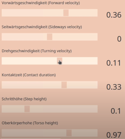
- The interactive Web-UI allows any user to control and stream the robot in real time on any device, and even connect a gaming console controller! Especially this part of my project might offer a lot of potential to get people excited about those robots and maybe interest a few people in getting into robotics, considering I tested this Web UI in my family and everyone had a lot of fun with it.
The mechanical side of things
I started working with my "Anycubic i3 Mega" 3D Printer, by just printing out prototypes of different servo types, to get an idea of what I'm dealing with. At the same time, I was reading up on the entire theoretical aspect (control theory and software development of real-time systems). As an (at-the-time) 16 year old student, I had no idea what I was dealing with so I had to learn by just trying stuff. After a few servo iterations I built a leg that served the same purpose, getting an idea of what it is like to build a more complex mechanism. It was quite colorful because I was trying out different filaments at the same time :)
I designed the actuator and everything myself, based on the QDD principle first introduced (to me, at least) by Ben Katz and that worked surprisingly well after a few printed iterations, but, of course, it was neither intended nor suitable for actual use in a biped. Stiffness was horrible and 3D printed tolerances are generally not good for backlash. Luckily, I never intended on making this first version actually walk.
I also tested Cycloidal drives and harmonic drives but did not want to deal with the complexity and added mass of so many bearings. Another factor was that my 3D printer didn't really like to produce repeatable parts so it would have been a nightmare to get multiple reasonably working cycloidal actuators printed.
Lastly, reflected inertia and thus backdrivability, along with torque output are the most important design characteristics for such an actuator, and planetary gearsets simply were the most realistic option for me.
However, I do believe a slightly smaller biped would still be viable with this actuator design, even when 3D printed. I should have used Carbon Fiber for the actual leg parts, but it was way faster (and safer for my lungs) to just 3D print them.
Roughly at that time, I got in touch with a local "research center" that promised to support me by enabling me to produce an actuator of my liking out of stronger materials like steel or aluminium, because that was one of the main lessons learned by my 3D printed experiments: It won't hold at this scale.
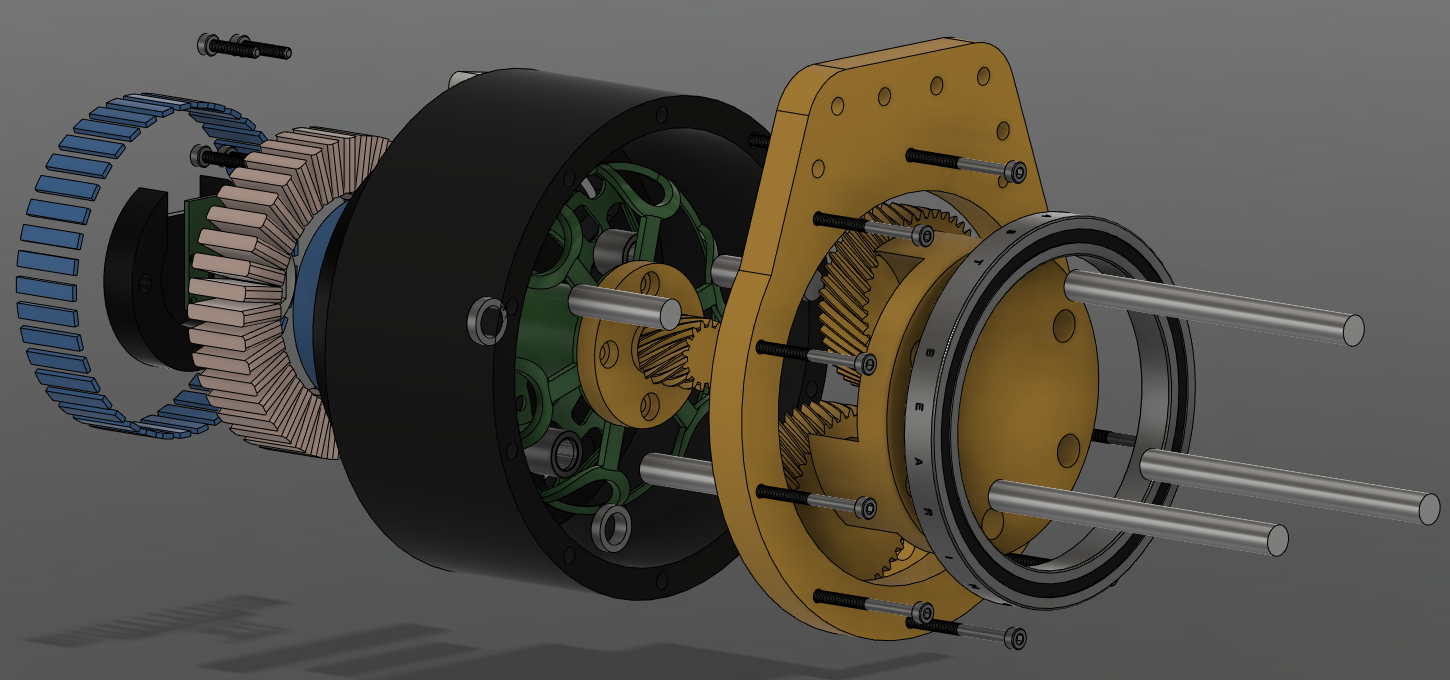
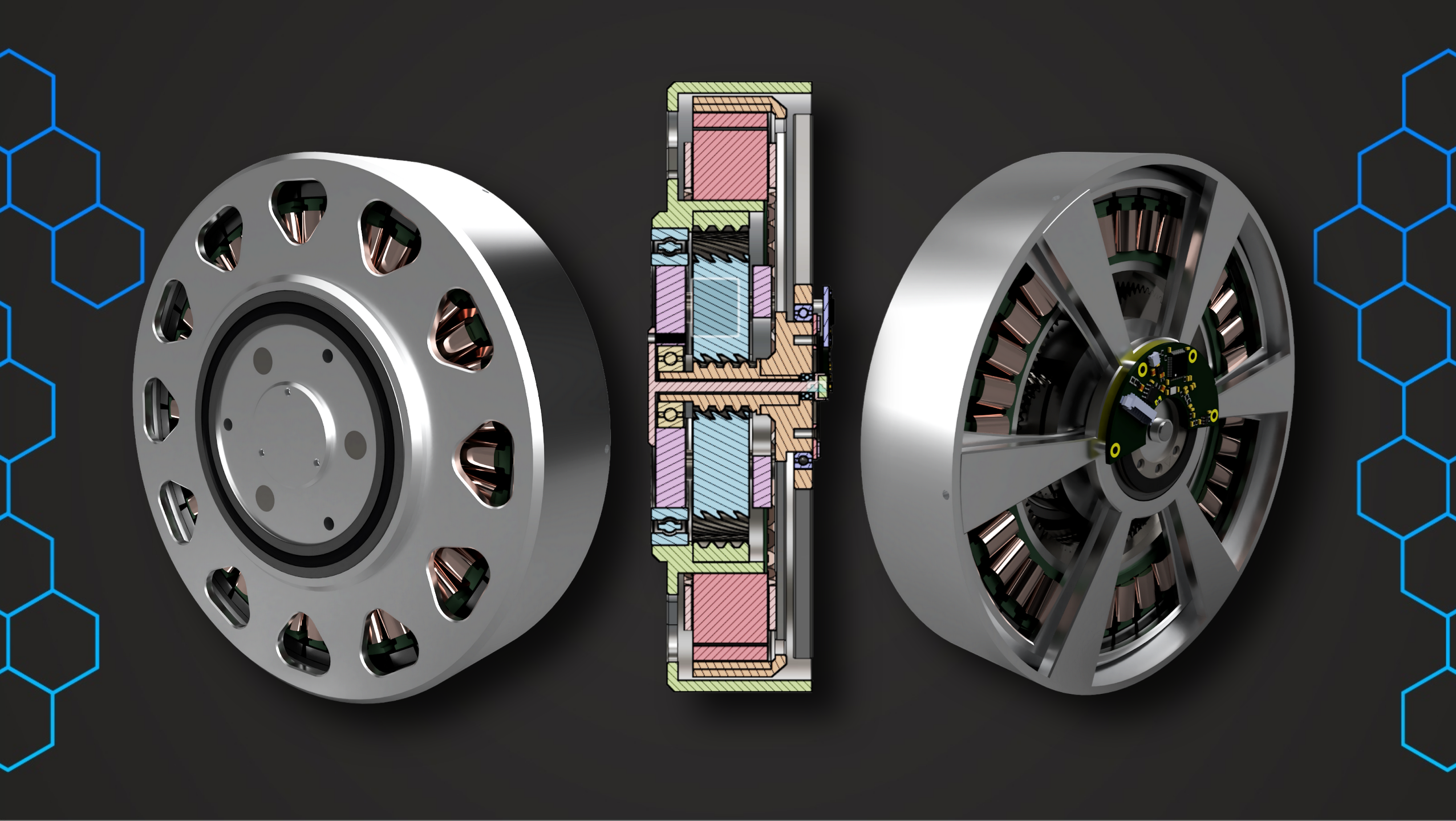
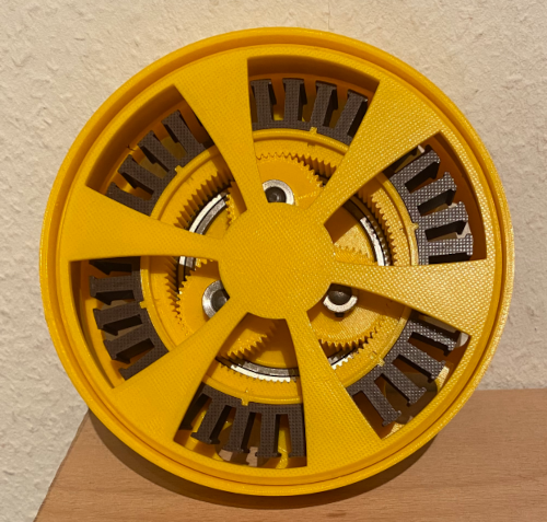
So I started working on a more integrated actuator version that improved a lot of the previous shortcomings and was designed for maximum peak torque. With an outer diameter of 160mm, a mass of about 2kg and a thickness of 42mm, this is a Ben-Katz-style quasi-direct-drive (QDD) actuator made for human-size humanoid / bipedal robots.
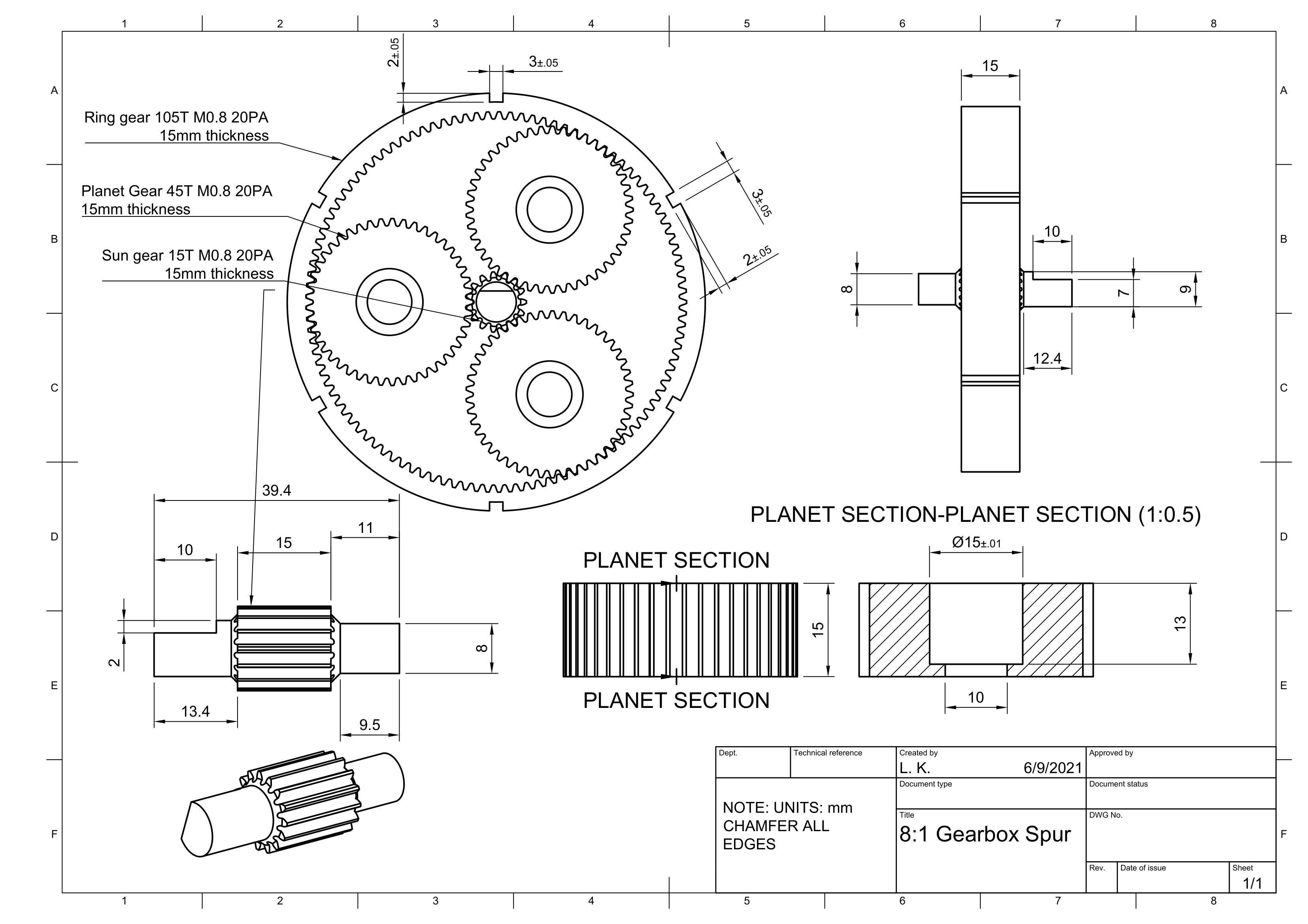
A 137mm-OD stator from JYStator, a custom planetary gearbox from Bestagear, the encoders and the magnets are the only OEM parts, the rest (enclosure, planet carrier, rotor, jigs for assembly) will be machined out of Aluminium 7075.
I calculated a peak torque of 110-130Nm based on motor simulations using Ansys Electrical and validated all parts for this design torque in Ansys Mechanical (initially F360 as well) using Static Stress and Fatigue Analysis tools.

I already had BOM, Assembly Plan and CAD for everything, then COVID hit and everything came to a stop. To be able to keep working on the project, I quickly turned to the software side of things. The closest I got was a 3D printed version that functioned as an "assembly test":

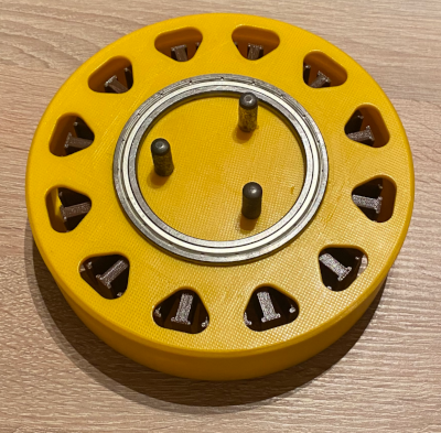
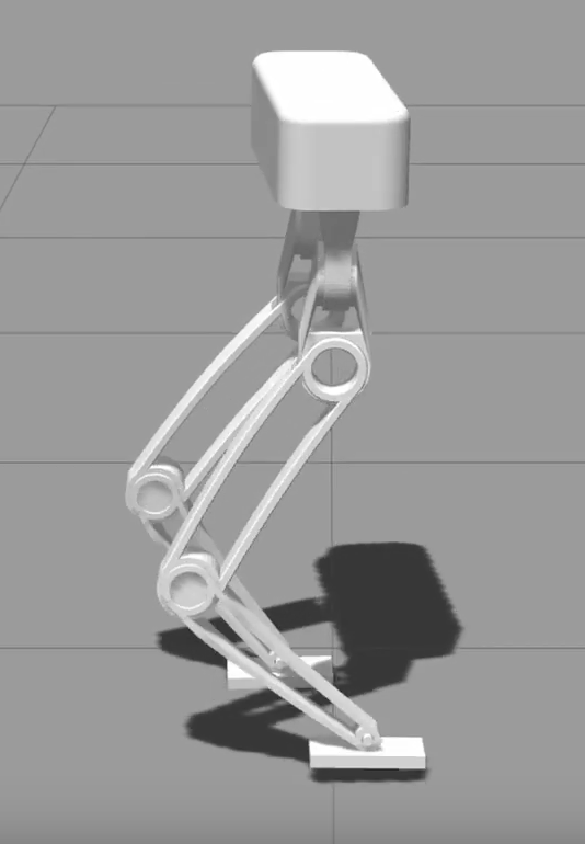
Once I was satisfied with the assembly complexity and the servo design in general, I combined the actuator into my latest full bipedal robot design to have a reference design for the simulations I was planning to do.
I did try a few iterations of the more common leg setups before getting to this one, as can be seen in the first video, but I thought about how the human body works and tried imitating that in my latest version.
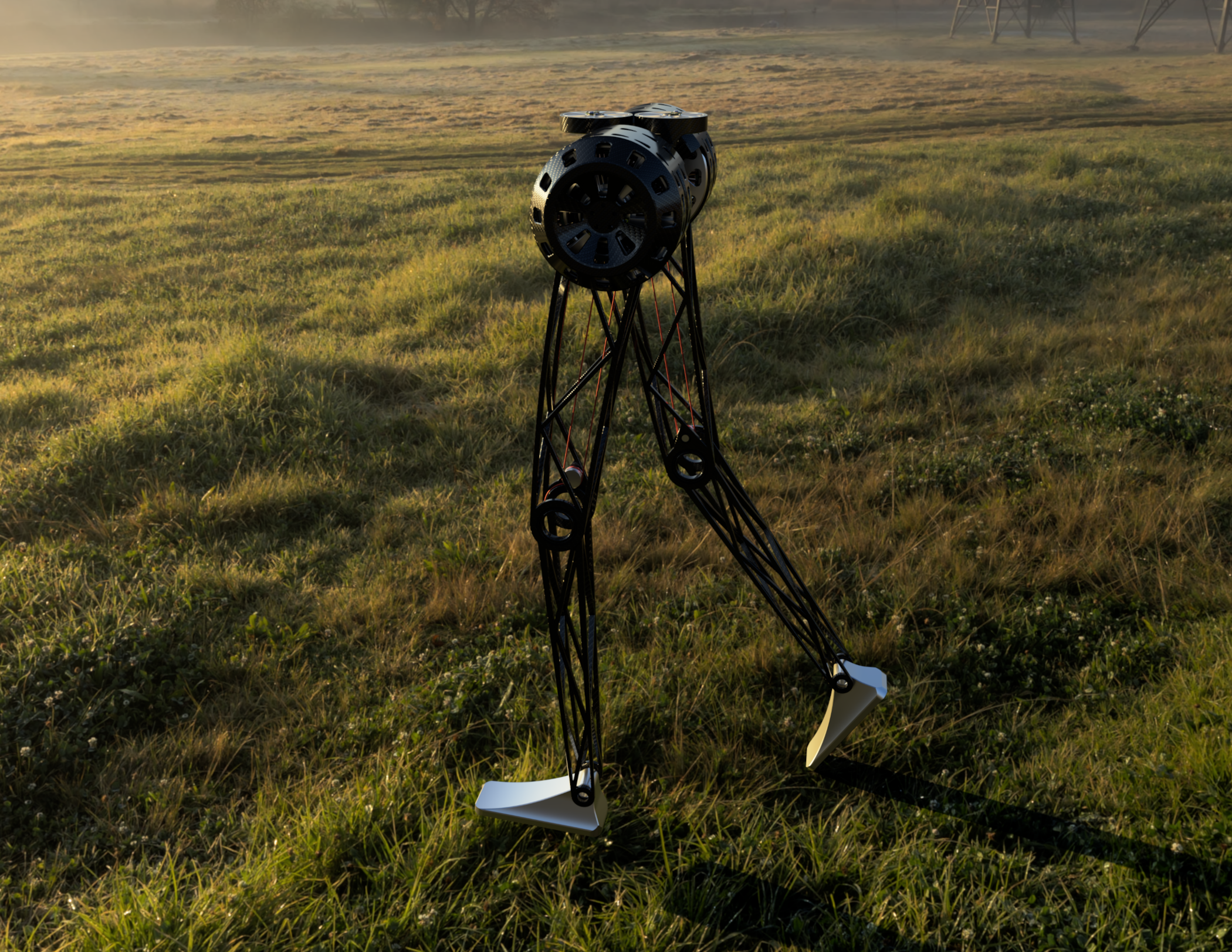

The main component in the biped is the servo. Each upper leg contains one for the hip degree of freedom, and another one for the knee joint. The torque is transferred via a capstan drive, which is integrated into the leg link itself.
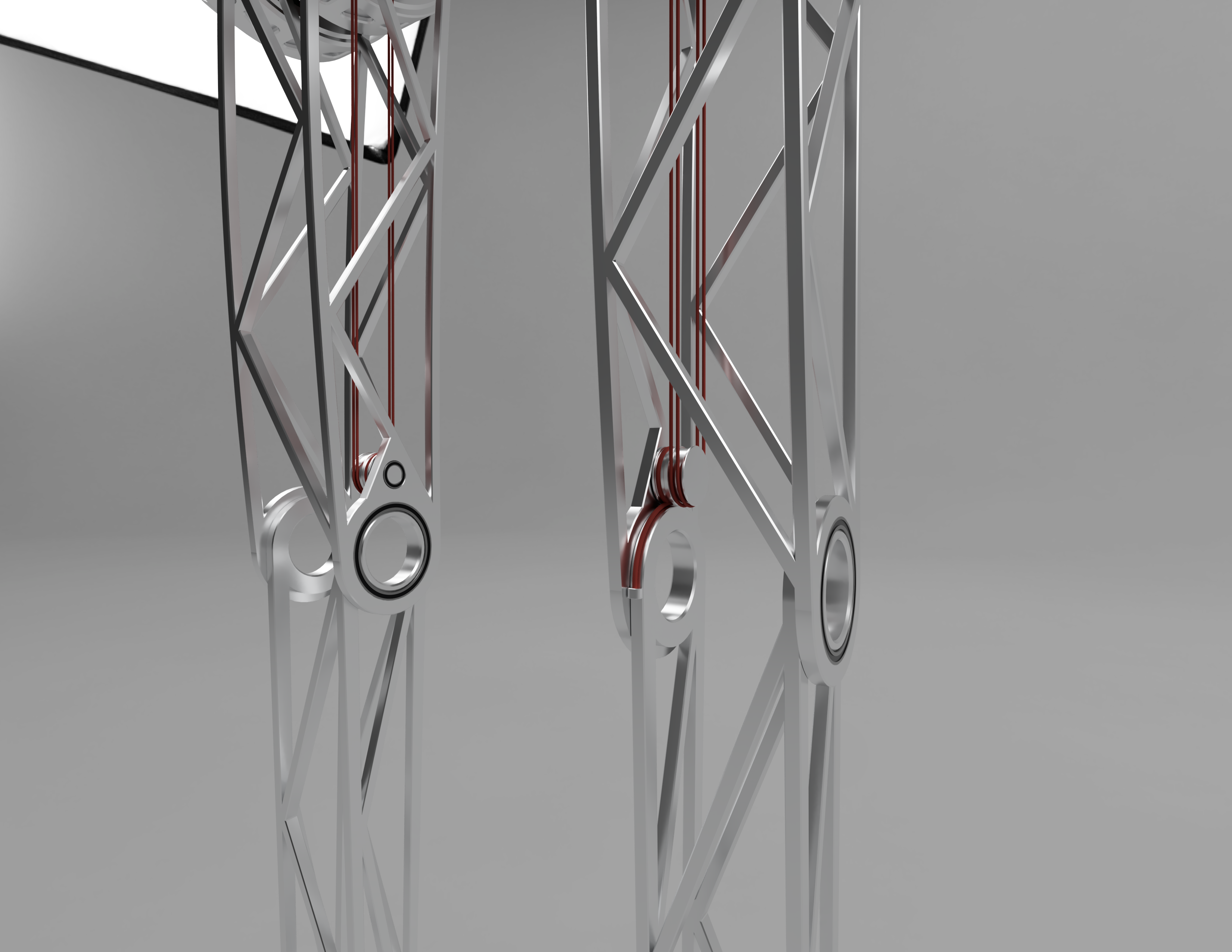
I am aware this will be quite tricky to get working properly, but I think the way I designed it, the reduced inertia of the leg link should be worth the trouble and doable based on previous research. It allows the leg (and thus the robot) to be much more agile by concentrating the mass around the torso, instead of having a separate actuator at the knee.
I am planning to use something similar for the foot, even though I want to experiment with 2 degrees of freedom there, because I already designed the hip layout based on the human body and would like to follow this principle by using synthetic "tendons" for the foot. I did test the biped with a passive ankle as well, though, and the performance differences were minimal, at least on flat terrain.
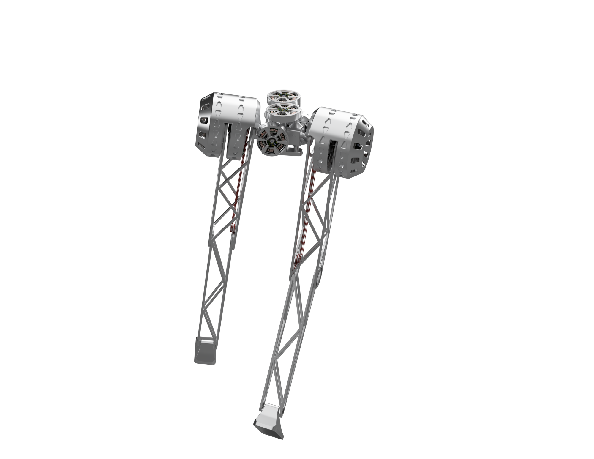
To further reduce moment of inertia, the knee actuator is actually fixed to the hip support bracket as well and compensates for hip rotation via software, which means that only the truss structure is moving around.
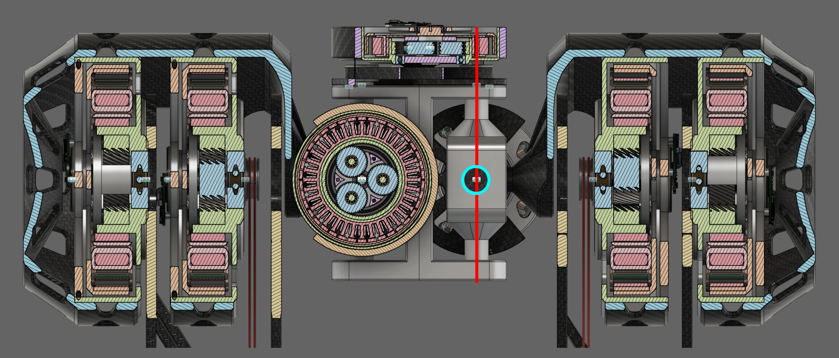
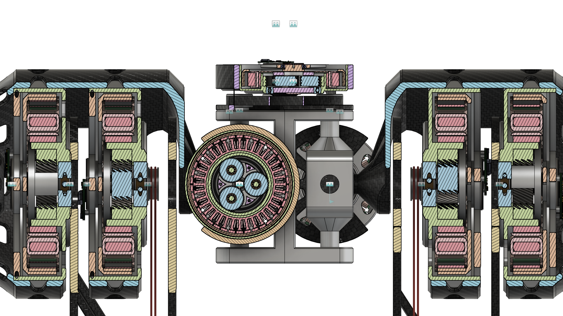 The hip actuators in the middle of the torso are scaled-down versions of the knee actuator and provide the remaining 2 degrees of freedom for the robot. The upper actuator is offset by a belt drive or potentially another capstan drive to make the assembly more compact and allow greater range of motion for the legs.
As you may have noticed, it has a slightly different kinematic structure than most robots out there. In my summary video right at the top, I use a simpler layout as a starting point, because it might be less intimidating for new users to see a more "serial" leg where each degree of freedom is clearly discernible.
So the upper hip actuators rotate the entire actuators on one side below it, including hip and knee actuators around the red axis, while the actuator in the "back" rotates only the leg around the blue circle, so "through the screen":

If you're wondering about the Carbon fiber, this was mainly to try out what the renders would look like, I will most likely start either combining CF and aluminium for those hip mounts or just use aluminium for the first prototypes to simplify the design.
In my opinion, the result looks quite similar to the human leg setup and offers some advantages in terms of mass/inertia distribution. The mass should be concentrated around the torso to make the robot more agile, which is the case with this approach.
Just imagine a 1.5-2kg actuator being swung around with the entire leg at speeds of up to 3.5m/s at the knee joint. The way I've designed it here, the entire leg should not weigh more than 0.5kg, which results in a very low moment of inertia for the entire leg:
All parts were tested in Ansys Mechanical for the expected stresses, and I am trying to find money to build a prototype of this version, of course with adjustments while I'm building along. The first step is to have the servo working well, after that, I will assemble the whole thing since the rest is "only" more or less complex mounting brackets.
 Keep in mind this is an exaggerated deformation scale :)
Again, since I try to be as open as possible about all this, the CAD, BOM and assembly instructions (still work in progress, of course) are all linked above and you could build this robot yourself, run my software on it and have it walk!
... And now the Software Stack!
You're now probably wondering the same thing I was at the time: Assuming I have a chunk of metal standing in front of me, how do I make it walk? Turns out there is no easy answer, and even though I was reading a bunch of papers about the control theory MIT etc. were developing, I was initially quite confused.
I don't want the robot falling down like that in real life:
What fascinated me the most was the "proper" way of making it walk, so not semi-static kinematically determined gaits that do not adjust based on the environment or outside factors, but rather a more dynamic, force based approach, where the contact forces for each foot are determined for each point in time, instead of just telling the foot where to go when. While projects like the mjbots quad have shown great success with such an approach, I do think model- and force-based controllers have more potential, and also I just found them more interesting :)
Additionally, I loved the concept of Model-Predictive-Control ("MPC" below) before I even fully understood it, because to me it was a sort of intuition I was giving the robot about itself. For Model-Predictive-Control, you obviously need a model so I obsessed about how to model systems in the well known state space form for a while.
Keep in mind I have no formal education on anything other than high school math so I started with googling one term, then not understanding the other terms in the explanation and so forth.
Eventually, I started working out basic control theory like cart-pole during my Christmas holidays, to get a grasp of how to work with all of this new math that was (and still mostly is) way above my head, as well as the simulation software (Gazebosim) I had chosen to use for my work:
The most important papers I will mention here are Dynamic Locomotion in the MIT Cheetah 3 Through Convex Model-Predictive Control and Highly Dynamic Quadruped Locomotion viaWhole-Body Impulse Control and Model Predictive Control, if you want to read more just go down the "References" rabbit hole, that's what I did.
TLDR: The main controller is split up into two parts, the high frequency (4kHz) leg impedance controller, which roughly makes the leg act like a damper on contact, while generating torque setpoints for a desired position, velocity and acceleration, and a high level model predictive controller that generates the desired contact forces.
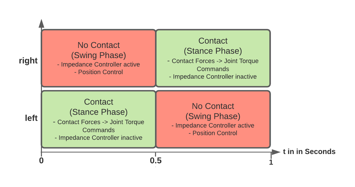
If the foot is in contact, MPC forces are applied by transforming cartesian space contact forces into joint space torque commands, if the foot is not, a polynomial swing trajectory is updated at a rate of 4kHz and followed by the impedance controller to get a step movement.

As far as I know, I'm the first one to be running the impedance controller and all high frequency code at 4kHz instead of the 1kHz, I tested 1kHz and only saw improvements going up, so I left it at 4kHz. The same applies to the MPC frequency, I've mostly seen 30Hz there. Again, this can be changed in a matter of seconds by changing one line of code.
For the contact "planner", I'm using a simple periodic function so far, but this approach is very flexible, as it just return a contact phase boolean for a given point in time.
bool get_contact(double phi) {
    return fmod(phi, 1) < 0.5 ? true : false; // fmod to handle wrap around that happens due to phi_offset for right leg where values become larger than 1.
}

// Contact Model Fusion for Event-Based Locomotion in Unstructured Terrains (https://www.researchgate.net/profile/Gerardo-Bledt/publication/325466467_Contact_Model_Fusion_for_Event-Based_Locomotion_in_Unstructured_Terrains/links/5b0fbfc80f7e9b1ed703c776/Contact-Model-Fusion-for-Event-Based-Locomotion-in-Unstructured-Terrains.pdf)
// Eq. 1
double get_contact_phase(double time, double t_stance_temp) {
    return (time - get_last_contact_swap_time()) / (t_stance_temp * 2.0); // Multiply t_stance by 2 because the function returning a discrete contact phase base on phi already splits it up into two parts.
}
To figure out the leg controller, which is also using an internal model in standard manipulator form to cancel out Coriolis and centrifugal forces as well as gravity, I built a kinematic model of the leg in a Jupyter Notebook using homogeneous transformation matrices, see here. From there, I tried using the Euler-Lagrange formulation to find the equations of motion, but that took even longer to compute than the 45 minutes it took for the closed form solution I found in this book, so I used those.
Once I had them, I added a PD controller to the control signal, which works in cartesian space and uses the end effector Jacobian to transform the forces into joint space torque commands. The full term is quite well known and looks like this:

The proof is trivial and left as an exercise to the reader :)
As soon as that worked in Python, I reimplemented it in C++ and gazebo to test it in a more realistic scenario and after a few months of figuring out the bugs, I actually got it working!
This is the relevant video:
As you can see, robustness testing played a big role for me from the beginning, because I was aware that running it on the actual hardware is a whole different task. Because I didn't want this robot to only function in a simulation, I thought about how to test the controller for real world conditions, and started by doing what you can see in the video, changing the robot on the simulation side, without telling my controller those parameters have changed.
Again, the fact that I could change the entire leg configuration from a single header file in a matter of seconds allowed me to do that quite quickly, as you can see between 1:36 and 1:50 in the video. This did result in a 4MB source file because I didn't allow a single simplification during the calculations in the jupyter notebook, but has saved me quite some time in the long run.
The video above should show that the impedance controller is robust, even to pretty extreme uncertainties for the controller. There is also no "cheating" going on, the controller is completely decoupled from the simulation, the same way it would be from a real robot.
I also considered SimBenchmark...
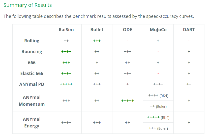 ...and tested my controller using both Bullet and ODE, which seem to be the most realistic options Gazebo offers.
So back to MPC: My plan was to implement the now so famous quadrupedal software solution for a bipedal robot, with some adjustments along the way, and when I get there start improving what I can. Spoiler: It was a littler harder than that :)
"Model predictive control (MPC) is an advanced method of process control that is used to control a process while satisfying a set of constraints." - in other words: It's really cool.
In my eyes, it allows you to give the robot a model of itself, and then let it optimize its motion based on that intuition it has gained. Most importantly, it uses the model to give predictions about the robot during the prediction horizon and generates a sequence of control actions for that horizon in order to stabilize the robot.
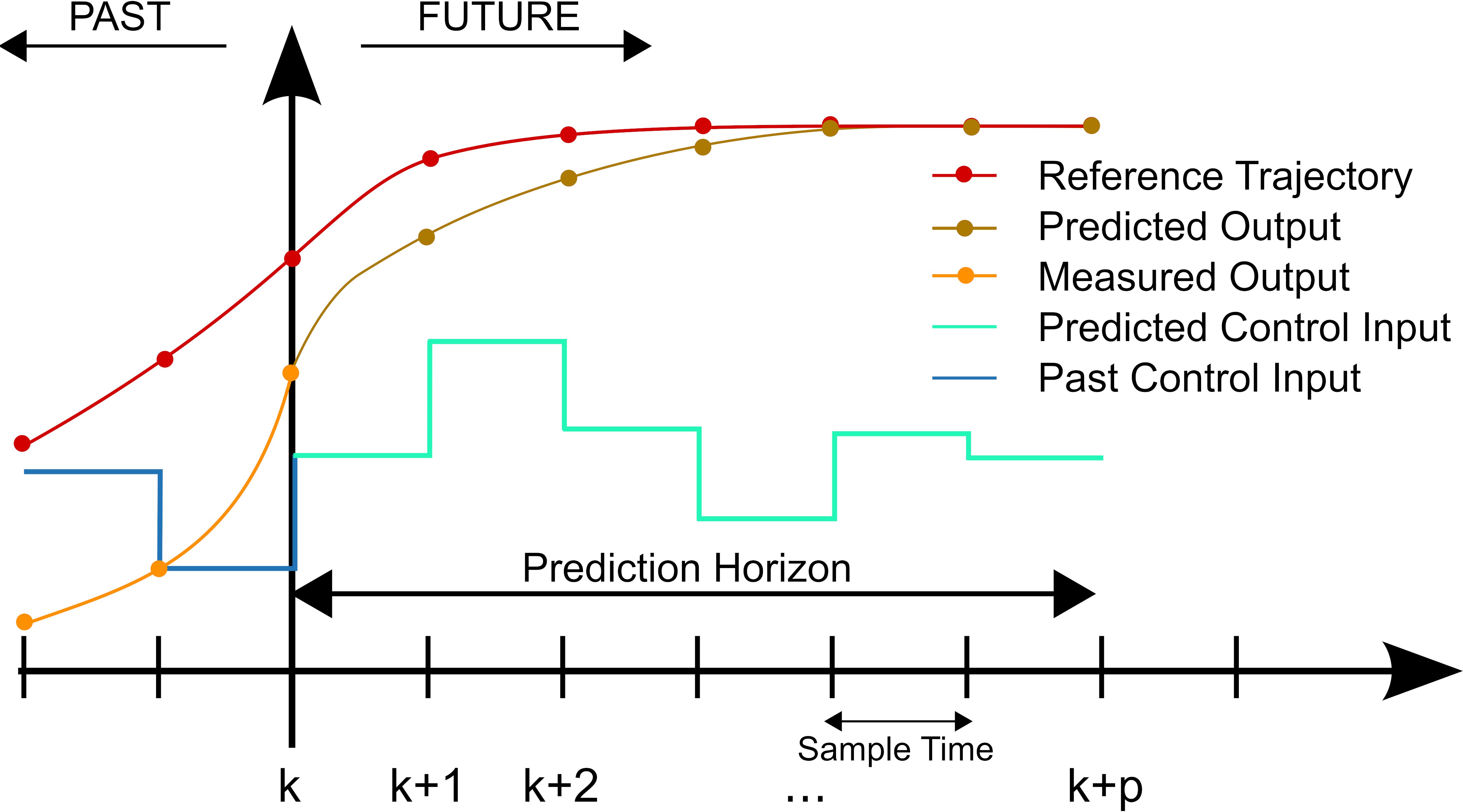
Additionally, because it's being updated online, i.e. in real-time (50 times a second in my case), it can react to external disturbances extremely well, because it knows what the robot will do in the future and it incorporates this knowledge into its control action:
As if this wasn't enough, it respects the constraints you give the optimization problem - if they are reasonable - such as force limits or velocity limits or torso height limits, anything you want, for all time steps.
Similar to the leg model, I started out in Python and got a feeling for the state space model of a point mass that I was going to use, as well as the optimization framework CasADi, because those were completely uncharted waters, too. I then combined the two, building a basic version of this model predictive controller using CasADi, without any gait planning, just a model predictive controller stabilizing a point mass in a purely mathematical model.
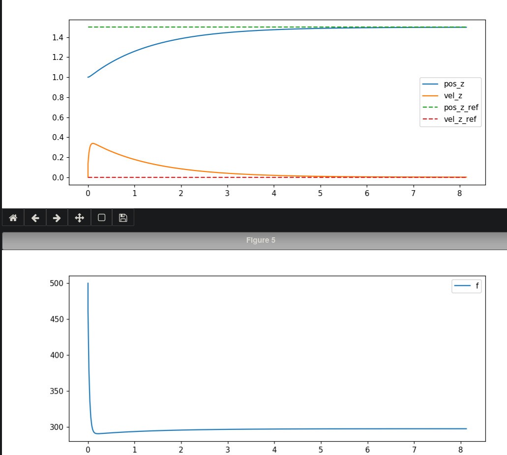
Once this worked well enough, I just expanded the controller step by step to make it more realistic: Periodic gait... ... adding force constraints...
for i in range(N): # Friction cone constraints.
    # -mu * f_z < f_x
    g += [-mu * f_z_left - f_x_left]
    lbg += [-inf]
    ubg += [0]

    # f_x < mu * f_z
    g += [f_x_left - mu * f_z_left]
    lbg += [-inf]
    ubg += [0]

    # -mu * f_z < f_y
    g += [-mu * f_z_left - f_y_left]
    lbg += [-inf]
    ubg += [0]

    # f_y < mu * f_z
    g += [f_y_left - mu * f_z_left]
    lbg += [-inf]
    ubg += [0]
...
...and much more!
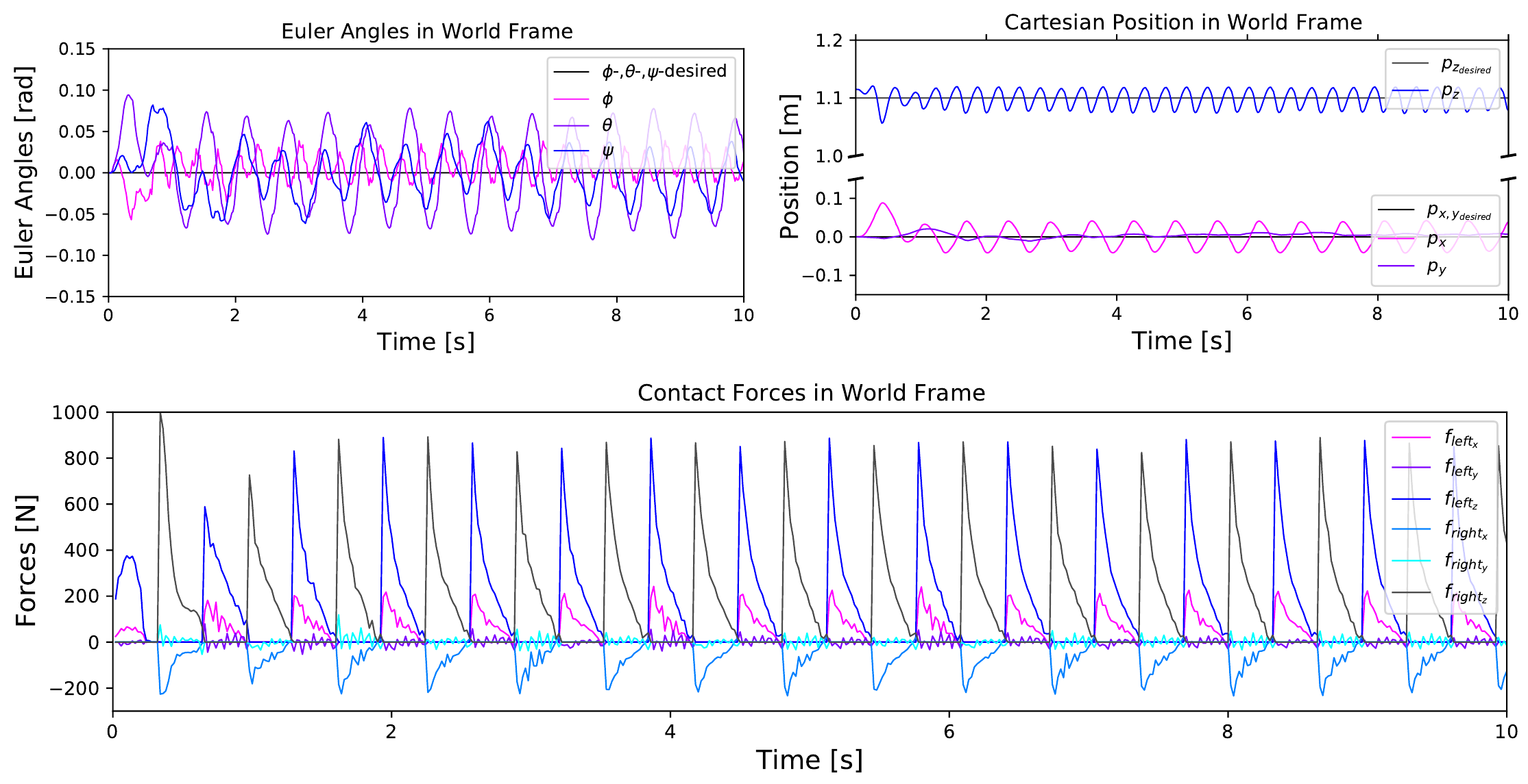
At some point, I thought I would have it working well enough in Python to go over to C++, the plots indicated it was walking with a positive velocity while keeping the torso's orientation stable, so I used the CasADi NLP (nonlinear programming) export feature for the optimization problem and re-implemented everything else around that optimization problem in C++.
Delay Compensation was one of the tricky issues I had to figure out pretty early on, because it only occurred in the more realistic simulation Gazebo:
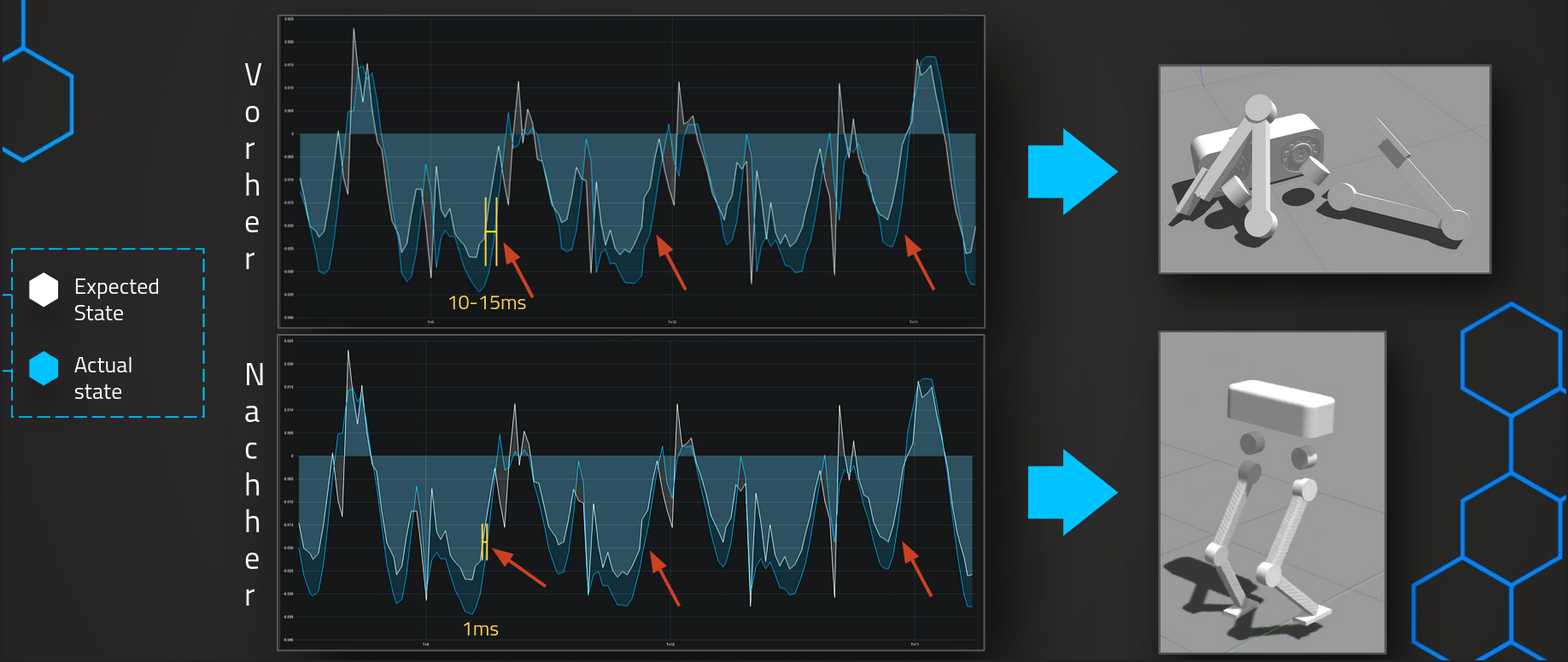
The controller was not compensating for the time it takes to solve the optimization problem, so the calculated control action was out-of-date by the time it got to the robot, which made it fall down pretty violently. After simulating the discretized state space model for one time step and using this compensated state for subsequent calculations, the discrepancy was minimal and the robot was able to stabilize.
More specifically, a main MPC loop runs at 50Hz, which prepares the optimization problem, updates desired torso trajectory, planned gait for every time step in the prediction horizon and fetches the latest state from the simulation.

I run detailed timing analysis on each code block on each thread and it turns out 95% of the MPC loop execution time is taken up by the NLP solver, with about 10-15ms on average. This is due to efficient usage of Eigen, which precompiles almost all code and thus takes up under a millisecond on average per iteration. The conversion from Eigen to CasADi data structures is also done using memcpy to keep overhead low. For the rest of the optimizations, you'll have to dig into the code yourself :)
This also revealed IO blocks that made the entire controller seize, of course that was an easy fix by using async IO, more on that here.
 It is important to note that I actually do use a nonlinear solver instead of a quadratic solver like qpOASES from the beginning, and that choice was intentional. I saw QP's being used everywhere in the literature, but in my opinion, nonlinear optimization will be necessary down the line anyway, in fact I already use it for some constraints, and it provides much more flexibilty because the optimization problem does not have to stay perfectly convex.
Here's a simplified overview of what the MPC thread is doing 50 times a second:

Now getting back to the original topic:
At this point the controller spins up almost 10 threads in the background, but the most noteworthy ones are the aforementioned MPC thread and the two leg threads. Those threads fetch the last robot state at a much higher rate (4kHz currently), process that info based on gait phase and either apply the MPC desired contact forces, or follow the polynomial foot trajectory that is generated based on desired foot positions in the future.

Lastly, I also use Docker to be able to run the full setup on any computer within seconds, and Github Actions to continually test my controllers performance using those docker containers. There is a simulation container and a controller container, both of which can be run with a single shell script that also handles logging (the controller currently logs at a rate of 5-10MB/s, mostly because it's uncompressed CSV).
The Github Actions CI is still a work in progress, but the idea is to have a suite of actual simulation scenarios being run in the simulation, like stepping in place, walking at different velocities, turning in place etc. and check if the energy used is within an acceptable range, if not, mark the integration test as failed.
To implement this, I introduced a real-time factor into my controller, which slows the control loops and the internal controller time based on an environment variable passed to the Docker container. Thus, the much less powerful Github Actions VM's can still run the resource-intensive physics-based simulation at a real-time factor of ~0.3.
Each controller run increments a counter so no logs are logs, and the "run-sim" wrapper shell script handles copying and renaming the gazebo replay file.
Since I can't really go into detail, I will refer to Github issues and the "Logs" tab of this project for more detailed explanations, or you can just read the source code :
I already gave it away right at the top, but this is the result:
A bipedal robot inside Gazebo Bullet, being controlled by a web UI in real-time, fully open-source both hardware and software-wise. You can have the same result on your computer in a few minutes with a bit of tinkering, because everything runs inside Docker, that's a first in my books!
 I successfully tested walking for over 4 hours, aka until my SSD was full, which resulted in ~8km of distance traveled, with an average power consumption of 100W. Even though this number is very much theoretical, I did include safety margins, and the numbers overall are quite promising.
 I would like to thank everyone who helped me online, but especially SharkWipf had answers for anything Linux or software architecture related and always provided great feedback even outside of Linux, the previously mentioned WPBack, who spent so much of his free time on this project and is one of the most patient people (and teachers) I know, Quincy Jones for answering questions about C++ and a few other things, and lastly Daniel Berndt for handling a portion of the Javascript and HTML "fun" that I was happy I didn't have to handle :)
I started the hardware part about a year ago, right when COVID hit, and it became clear that getting the required parts from China would become a challenge, to say the least.
So I decided to focus on the software side of the project, to spend my time as efficiently as possible.
At this point I've mostly finished the software part, aside from some minor code cleanup and adjustments, and am currently looking into getting the servo parts milled, to test the software stack on the real robot!
I will keep this page updated with any progress I make, of course.