As said in the previous log, I managed to get my hands on a bunch of PCBs from the Rotor 2.
Here's the whole lot:
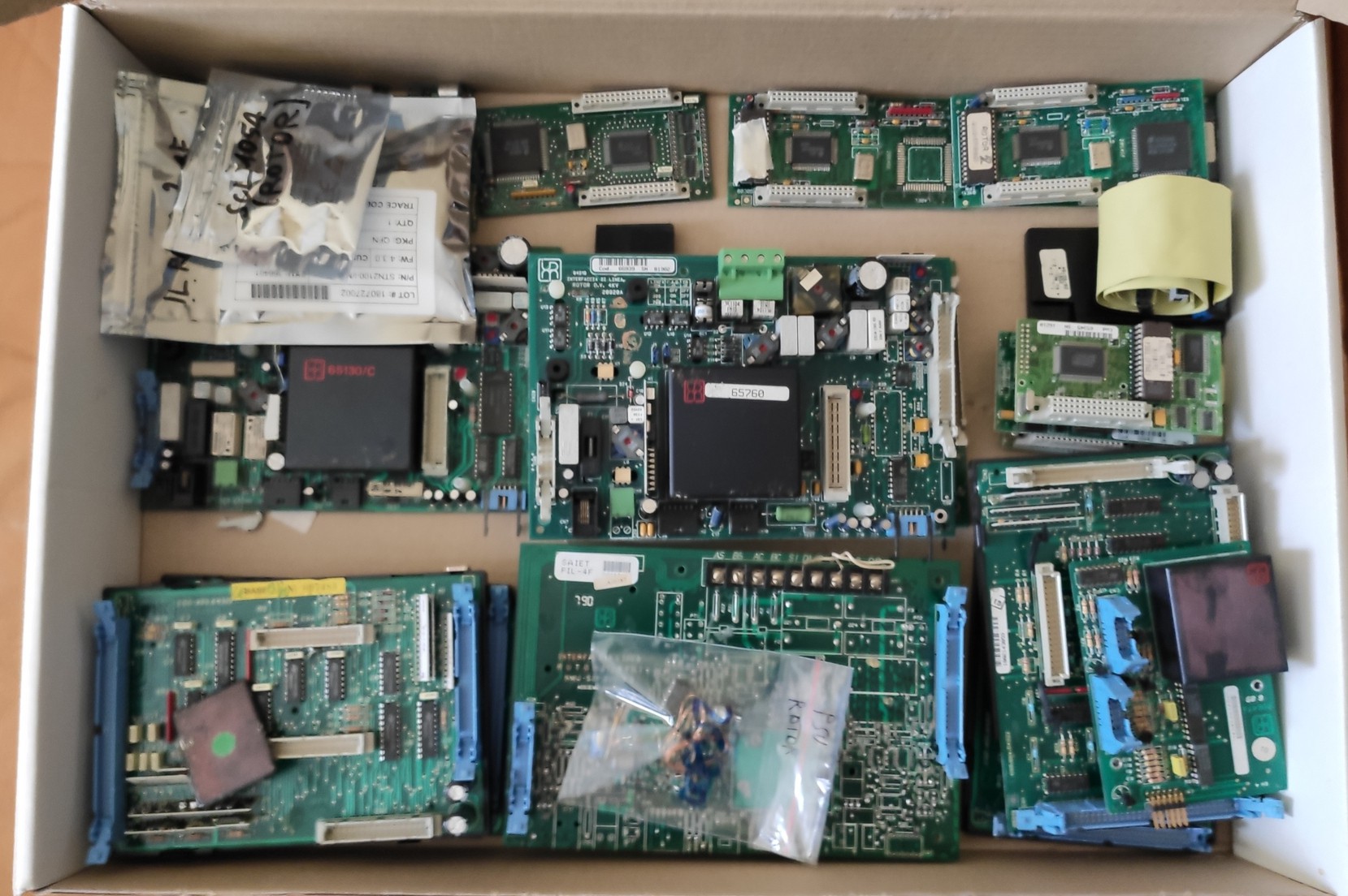
Aside from some ceramic modules which were broken in shipping (the eBay seller crammed all the boards in a much smaller box than this, with almost no padding...), the boards appear to be complete and in good condition.
I had a good look at all the stuff I've got (and at all the eBay auctions I could find that included photos of the internals) and I've got to say that the phone is a lot more complex that I anticipated.
There are four boards inside each phone:
1) The "line interface" board:
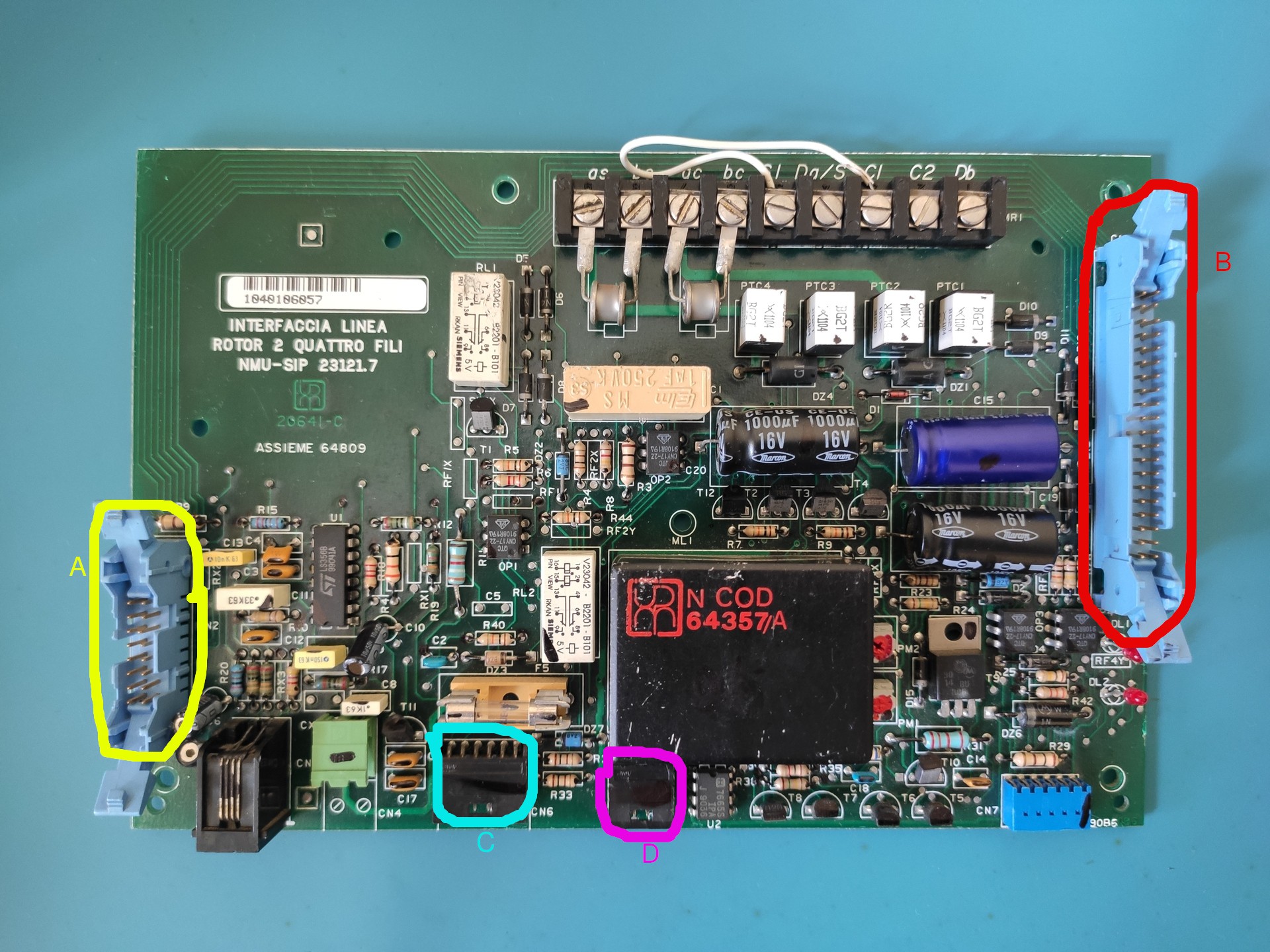
As the name suggests, this contains all the circuitry that interfaces the phone to the phone line(s). The section on the left, with the LS356B, is the actual "phone" part of the device. The connector marked as "a" connects to the keypad and the hook switch, while the RJ45 connector plugs into the headset.
The green two-pin connector connects to the integrated 6V lead-acid battery, which is recharged from the line and is used to power all of the internal components. This is presumably done to provide the short bursts of high current needed to power the electromechanical components (remember, the phone is spec'd to draw a maximum of 30mA from the line); it's wired like a double-conversion UPS, with all of the phone always drawing power from the battery.
Connectors D and possibly C seem to be used to connect to the internal/external coin safe, to enable the phone to know if the safe is opened/removed or simply full.
Connector B is used, alongside a normal 40-pin ribbon connector, to link the line interface to the main board.
The black box marked "64357/A", which I initially suspected to be the data modem, is actually the buck converter that provides the 6.75V for the battery.
2) The main board
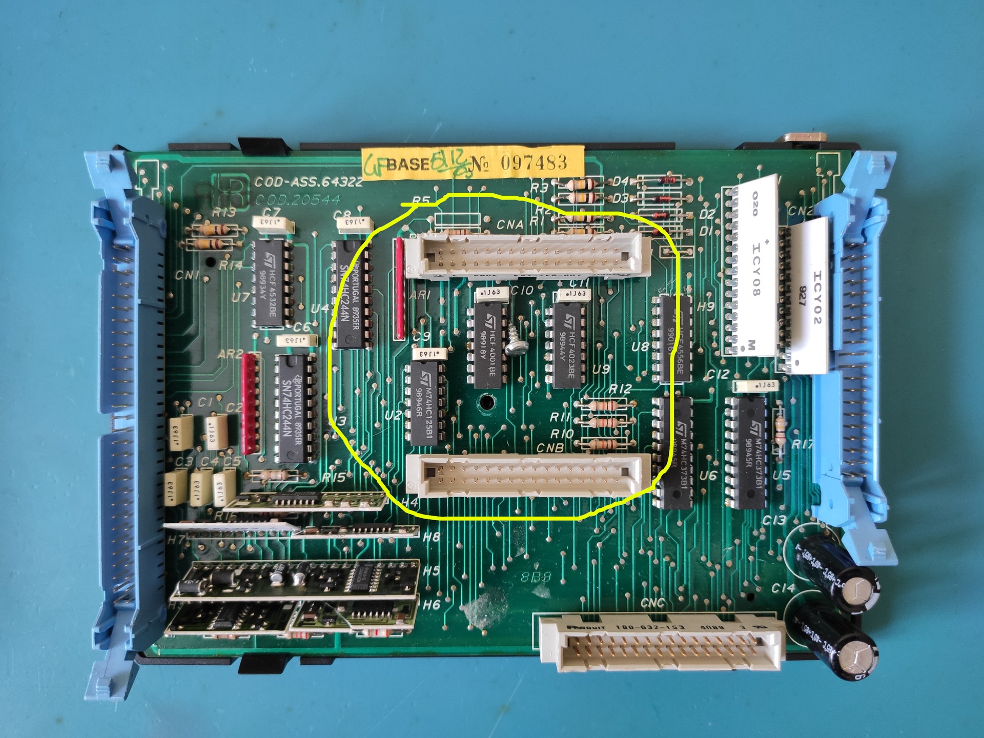
This board is housed on top of the mechanical section of the phone and interfaces both to the line interface (through the 40-pin connector on the right) and to the mechanical section itself (with the big connector on the right).
The actual CPU board plugs in with the two circled connectors, while the single white connector on the bottom is used for the configuration memory.
This board contains a bunch of 74-series logic and a number of ceramic modules (which I think are DC-DC converters)
3) The CPU board
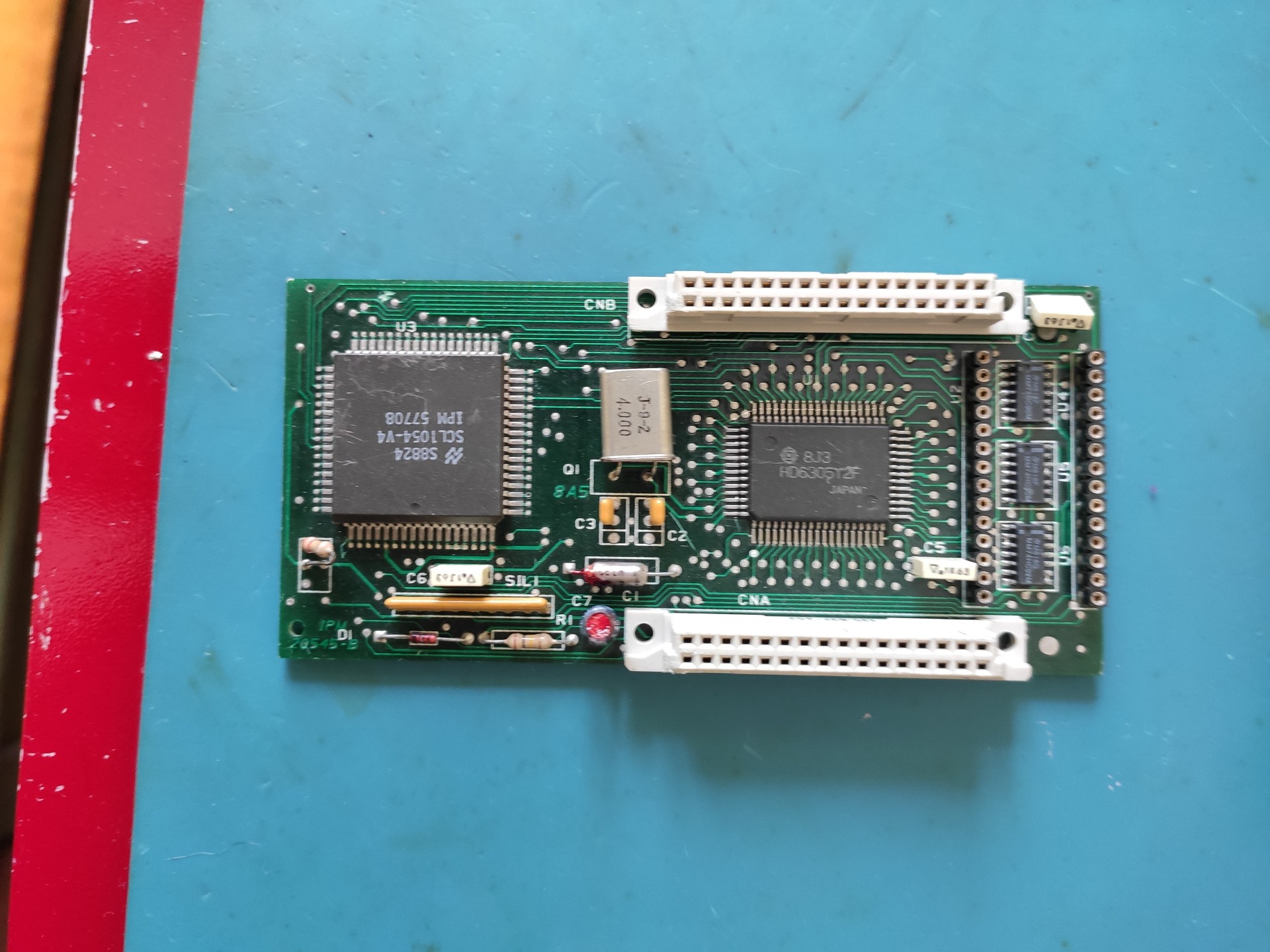
As the name implies, the CPU board houses the microcontroller that runs all of the phone, an Hitachi HD6305Y2. Luckily for us, this variant of the MCU has no internal ROM and it exposes its address and data buses to the outside world; the code is stored in a 27C256 EPROM which plugs in the DIP socket on the right. I've already dumped the ROMs and I currently have two variants, one simply marked "Rotor 2" and the other "Rotor 2 + L.I. v1.11" (L.I. probably meaning "lettore interno", "internal [card] reader")
The chip on the left is however a bit of a mistery. It's got what seems like a valid National Semiconductor part number, but I can't find any information about it. I suspect this is the actual modem chip I can't find any digital circuitry on the line interface board complex enough to be a modem.
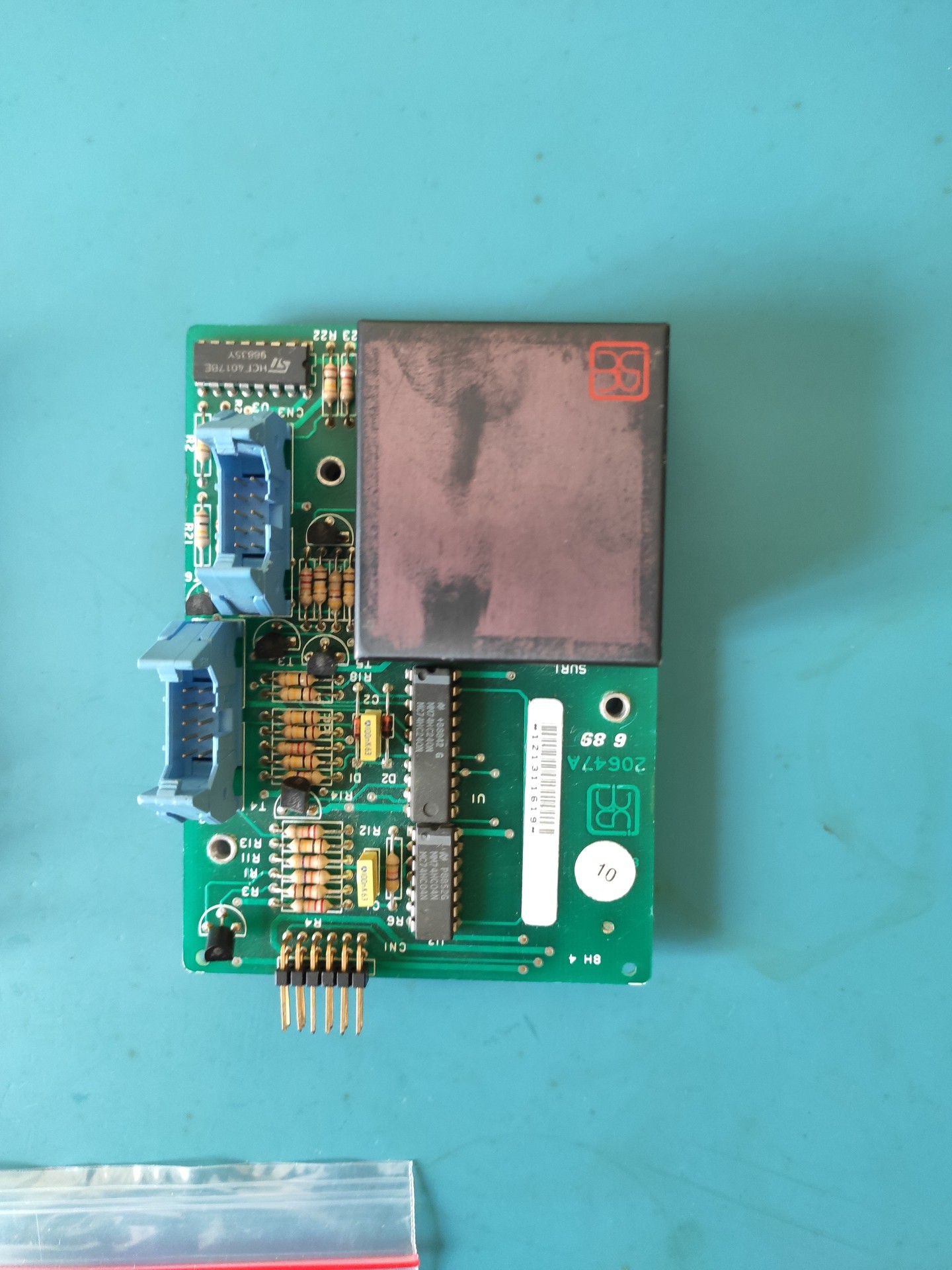
4) The "external RAM" board
This board, as the name implies, houses a battery-backed RAM chip used to store configuration data. Contrary to what it might seem, the big DIP chip visible in the picture is actually a 27C64 EPROM; the actual 2K x 8 RAM chip is housed under the ROM.(it's a really weird DIP socket with the pins that taper out, allowing you to house ANOTHER similar-sized chip under the socket).
There's also an Intersil ICL7665 chip used to monitor the battery voltage and alert the processor if it gets too low.
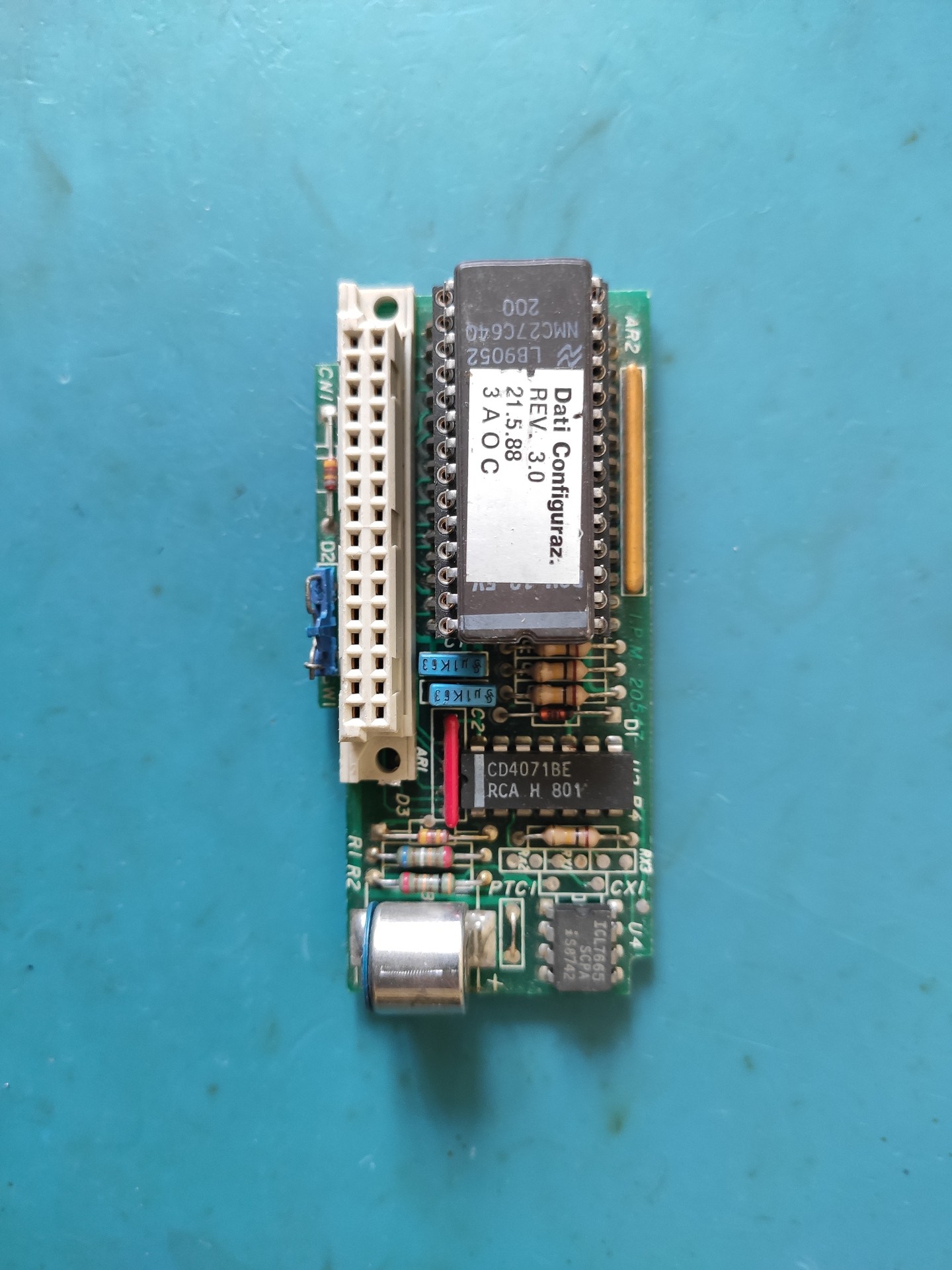
4) Mistery board
I have no idea what this board is used for; I also haven't been able to spot it in any of the pictures of the phone internals I found on the Internet.
It seems to plug into the line interface board using the connector on the bottom right, but again, I have no clue what it is supposed to be.
It also seems like I'm actually missing a board, specifically the one that is mounted in the middle of the mechanical section (I'd post a picture of what it looks like, but I only have photos from eBay auctions and I'm not sure if I can repost them here). Again, I know very little about this one; I suspect it MIGHT be the actual coin discriminator board.
What about the "other variant" of the phone?
In the previous log, I mentioned that, when looking at all the boards I had, I discovered that there's actually another variant of the phone aside from the Rotor 1, 2 and 3 models.
Here's what I'm talking about:
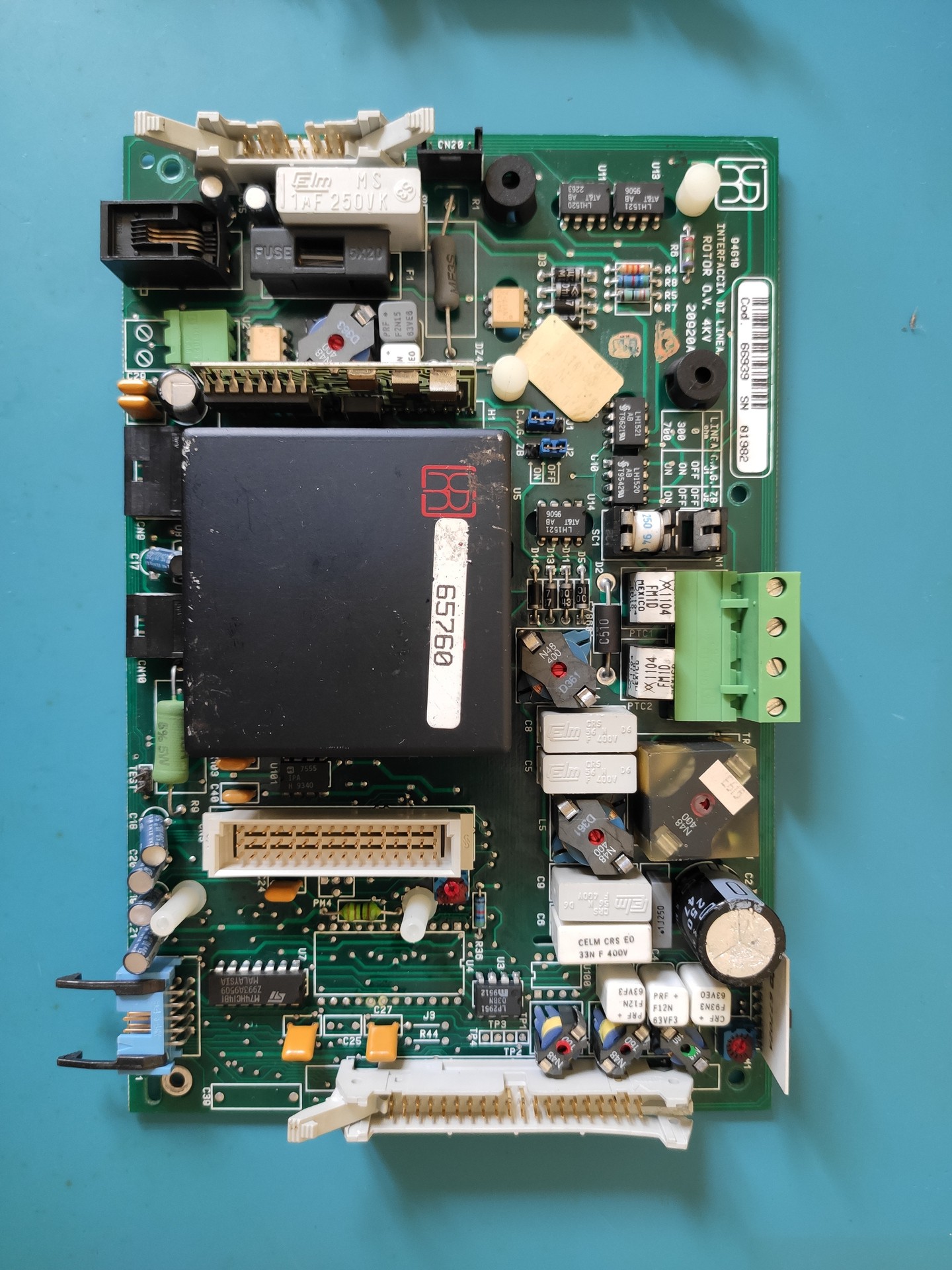
This line interface is marked "Rotor O.V." (presumably on the line interface board.OverVoice) and it appears to be a new revision of the two-wire board, radically different from the other ones; It's much more integrated and dense packing a lot of functionality in the same space. (the missing chip near the white caps is another modem chip, this time marked URMET/ItalTel v7308; I noticed just now I mistakenly photographed the one board I removed the chip from)
In this one, the CPU board actually plugs on the line interface itself, using the three-row connector:
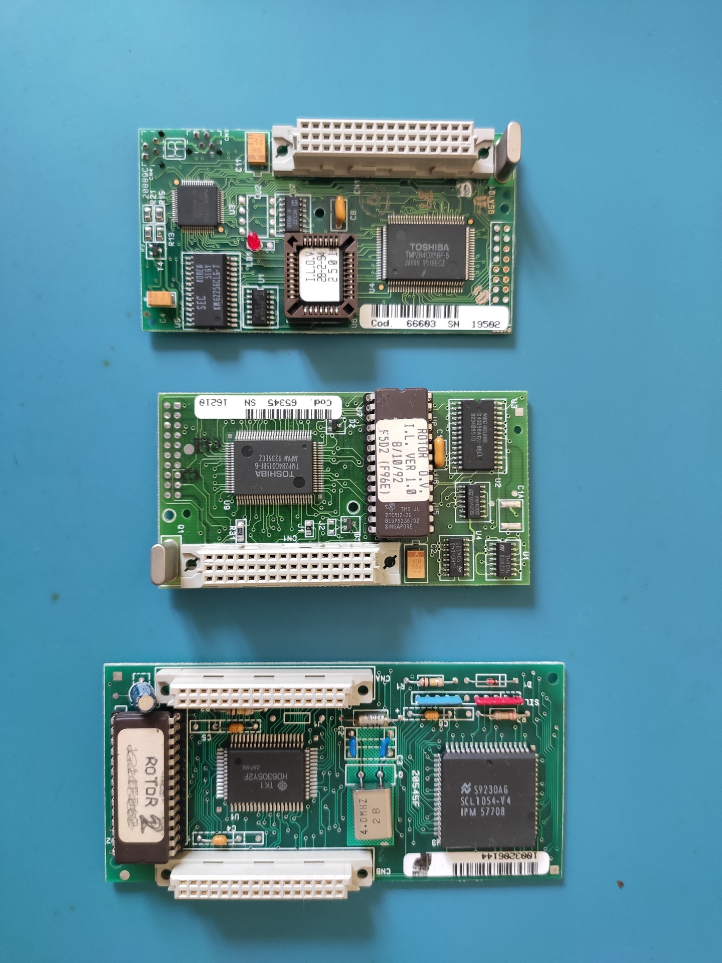
You can see two of the new CPU boards here, alongside an old one. The new board is equipped with a Z80-based microcontroller and a 32K x 8 SRAM; this puzzles me: why would they go with such a deep redesign of the whole line interface and CPU board a couple of years after the release of the Rotor 2 (note the sticker on the ROM saying 8/10/1992)? it just seems like a waste of money.
Again, I extracted the ROMs (only the DIP ones; I have to get a PLCC adapter) and there'll be more about those in the next logs (I have material for at least two/three more posts, one about schematics, one about the disassembly of the software, and one about the decapping of the mysterious modem chips, so expect updates in the following days)
Also, if there's anyone reading this that actually owns a Rotor (I doubt it, but it's worth a shot) and is willing to take some pictures of the missing board and the internal wiring, please contact me.
Discussions
Become a Hackaday.io Member
Create an account to leave a comment. Already have an account? Log In.
Hi, I have a rotor phone (according to the seller's specifications it should be the 2 wires version) but after replacing the pb main battery I obtain an "FS" + "E500" error. It should be External RAM Error. Checking the battery with a tester I read 0.87V instead of 3V. I want to change, but i'm not sure: is it a CR1/3N battery?
Are you sure? yes | no