The first thing I did after dumping the ROMs (since I was very worried they could start to lose data due to UV exposure and age) was trying to trace the schematics for all the boards.
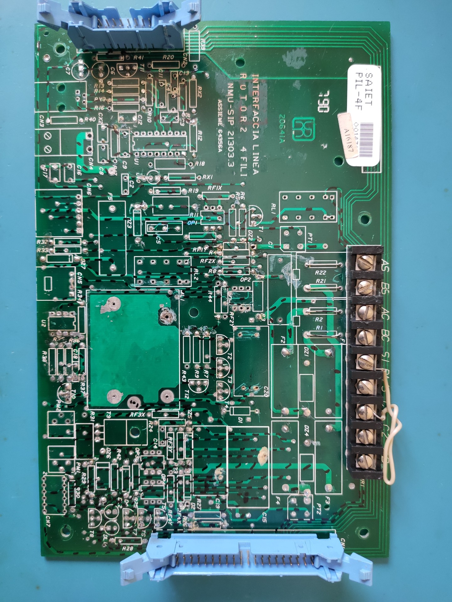
I started with the older "Rotor 2 4 fili" line interface board; I just went component-by-component, marking each pin I had traced to another component with a marker while writing the schematics on paper. Since I had two almost identical boards (they are a different revision, but have almost the same schematics and the component designators match), I just kept one with the component side up and one with the trace side up to speed up the process.
As I was getting to the end of the process, it dawned on me that the method I had used meant that I could have missed some traces (because I marked a pin as "traced" as soon as I reached another component instead of following every single trace); also, there's a couple of relays and coils that. being (almost) direct shorts, could have led to errors.
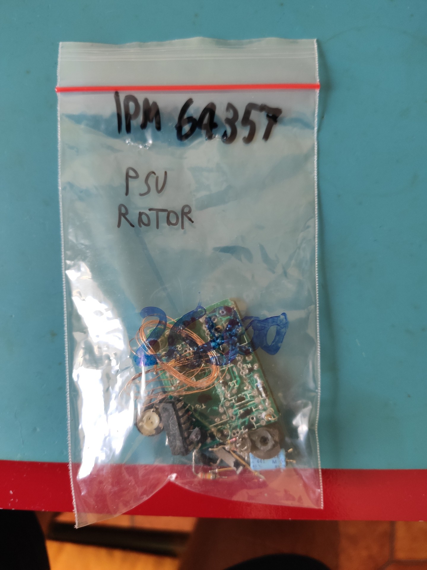
Since I had two boards and no phone to put them into (you either find complete phones or ones that have been "converted" and are missing all the mechanical parts), I decided to just strip the most beat up one of all the components:
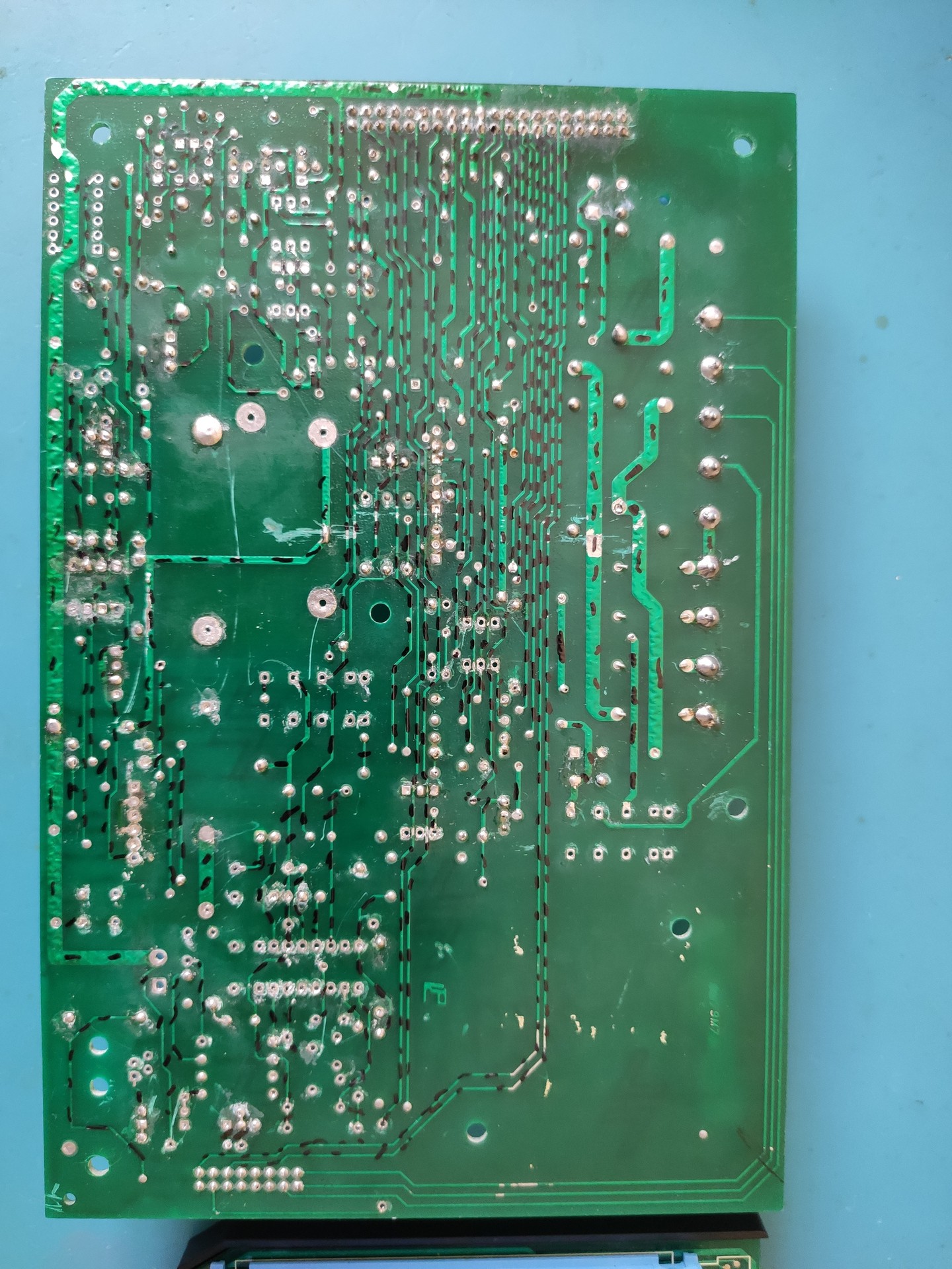
I then went trace-by-trace, marking each one of them with my trusty marker and cross checking with the schematics I had already drawn. After much tedious work, this is what I was left with:
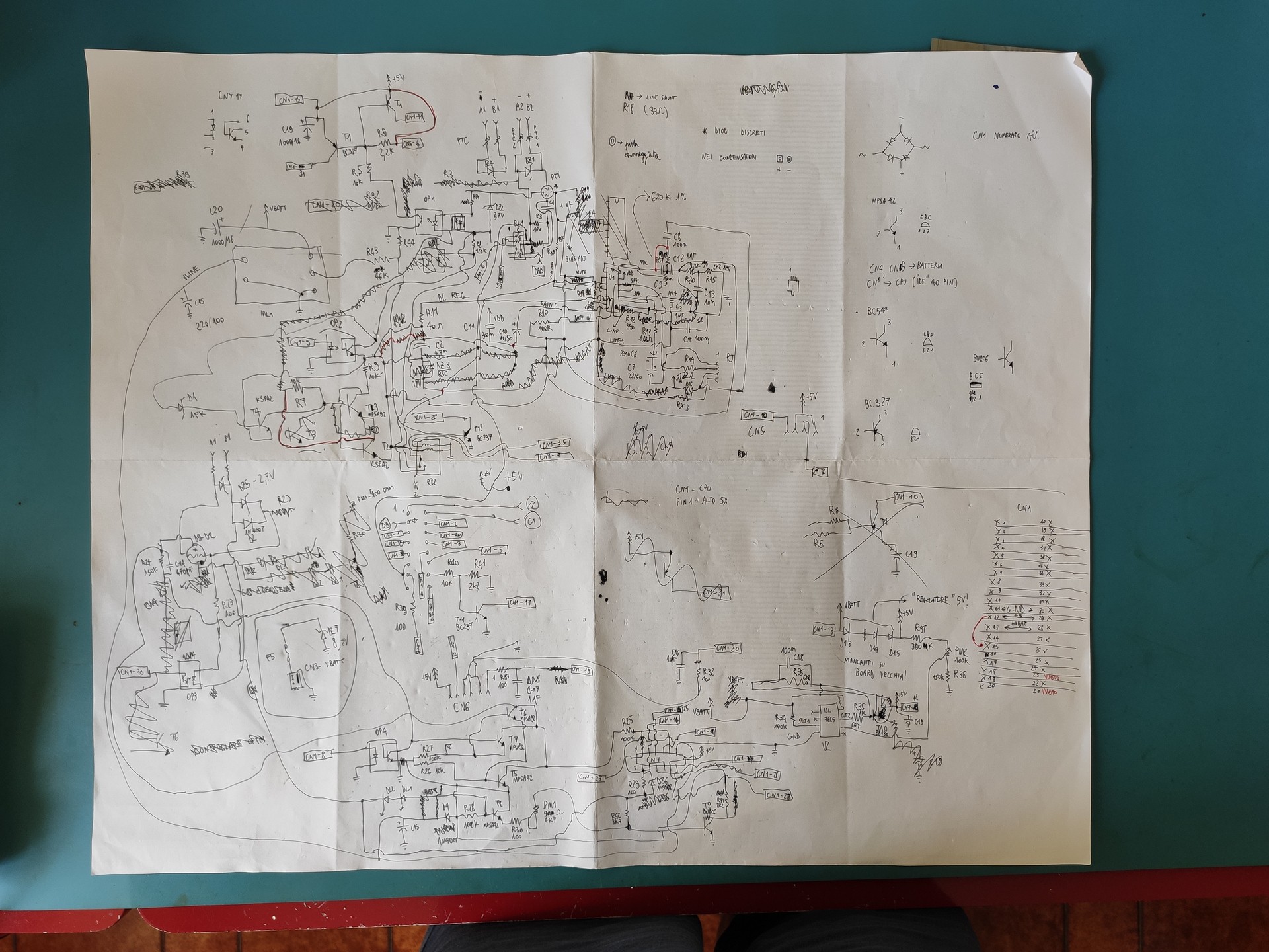
(the red lines are all the missing traces/mistakes I found after redoing all the work with the stripped board)
I still need to redraw this in Eagle, but I put that off temporarily when I realized this board does not contain the stuff I'm interested in (data communication circuitry and/or the card reader interface)
I then went on to investigate the content of the big potted module at the bottom of the board, thinking it might contain something interesting (after all, why would they pot it otherwise?). After spending much time with paint thinner, boiling water and various razor blades (didn't take any photos of that, sorry), I was left with a bag of broken components
and most importantly a schematic:
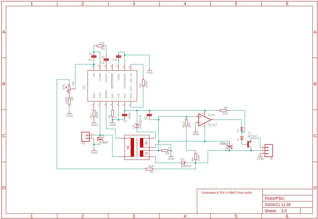
Turns out the module is a transformer-based switching power supply, used to charge the battery. Knowing this, the most logical possibility left is that the modem circuitry is all in the mysterious IC on the CPU board.
A bit disappointed that I didn't find anything really useful for my purposes, and sick of tracing PCBs, I decided to went on to track the software part; more about that in the next log
Discussions
Become a Hackaday.io Member
Create an account to leave a comment. Already have an account? Log In.