Close
0%
0%

Laser Timing Gate

An optical timing gate for sports events

Similar projects worth following
600 views
0 followers
In the NHL All Star game skills competition, players race around the ice to see who can set the fastest time. To bring a bit of that excitement to the local rink, I developed a simple optical gate and timer that can be used to see who's the fastest on your team. As an added bonus, it's based off of an ESP32 and hosts a simple web front end for the timer, which makes it possible to control remotely and display the time on a larger screen.

See https://github.com/xdylanm/timing-gate/blob/master/README.md

Goals

The laser timing gate is a simple stopwatch that is triggered optically for lap timing. It should be

  • eye safe
  • usable indoors or outdoors
  • be accurate to 0.01s
  • mountable on a tripod
  • battery powered
  • can be started by the athlete or a starting trigger
  • have physical controls and a display
  • have remote controls via a phone app or browser

As an extension, it would be nice to be able to pair two gates together to time one-way events, and integrate the light source & receiver in the same unit (only one tripod required per gate).

Scenarios

Athlete Initiated Starts

When an athlete initiates the start, the timing gate starts in an idle state when the beam is aligned on the photo sensor. When an athlete steps into the starting area and breaks the beam, the gate is ready. A starter/official can then arm the gate. The athlete can now start when ready. When the athlete moves and the beam reconnects, the timer starts. When the beam is broken again, the time stops and the lap is finished.

Design

The initial design is based around an ESP32, which in addition to providing the simple physical interface (buttons, LEDs, small display over I2C) can also provide a wireless connection over WiFi or Bluetooth. The onboard ADC is used to monitor the illumination level on a photoresistor, and a threshold determines if the light is at the "beam" or "ambient" level. Interrupts are used for timing. Two LEDs indicate status, and an onboard display will indicate the state of the gate and show the stopwatch time during a lap.

Interfaces

I thought I'd write up some detail in this section since this is where most of the interesting design choices came up (both in hardware and software).

Status LEDs

Two LEDs indicate status.

  • a red LED shows if the beam is attached or broken (on=attached)
  • a green/blue LED shows that the gate is armed and that the next action (beam connection changes state) will start the timer

These of course also serve as basic diagnostics and can be repurposed to show e.g. network status.

OLED Display

The OLED display is used to show the status of the stopwatch (e.g. Idle, Ready, the running time & lap time, etc.) and other configuration status. Visually it is divided into two sections: a title line (about 10 characters) occupying the upper third of the display, and either a subtitle line or up to 3 status lines in the lower two thirds.

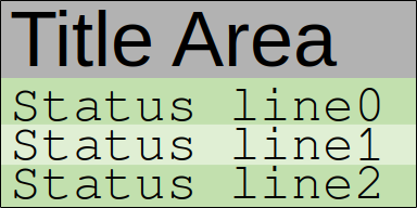
A third option (for the stopwatch time) centers the title area vertically. The DisplayManager class encapsulates this interface, and is composed of GFXcanvas1 and Adafruit_SSD1306 objects (thanks Adafruit!). With more time here, I'm sure a much nicer UI could be implemented, but the idea is to put that effort into the browser interface.

Navigation Buttons & Onboard Menu

I was aiming for a minimal interface for navigation, so there are two navigation buttons: "next" and "apply". This is similar to some interfaces on monitors. I eliminated the "back" action by adding that as a soft option in each menu, and similarly re-used the "apply" button to accomplish an "in" action. This works for small menu systems. The idea is that more complex interactions can be achieved through a remote interface.

The onboard menu only needs to include three categories: the stopwatch, light sensor calibration, and basic wireless configuration (i.e. enough to provide a remote interface). This also ensures that there is enough control through the onboard interface to operate the timing gate without the remote interface as a fallback. There is a state tree in the readme for more information.

Web Interface

To make the interface more accessible, the unit also provides a simple web front end. The ESP32 starts in AP mode. A connection to that WiFi network (currently hardcoded SSID & password, no connection to an external network) provides access to the web server on 192.168.1.1, which hosts a simple status page. The time status (ready, set, go) and running time are then displayed. Messages are passed from the physical unit (host)...

Read more »

BasePlate.3mf

3D printing file for the base plate of the case. Prints without supports. Holes for the screws to mount the sliding power switch must be drilled and knurled inserts added for the tripod mount (underside), TP4056 retaining clip and main board mount.

3mf - 50.04 kB - 01/03/2022 at 17:27

Download

TopShell.3mf

3D printing file for the top shell of the case. Prints without supports. Knurled inserts must be added for the screws holding the display board and for the connection to the base plate.

3mf - 65.54 kB - 01/03/2022 at 17:27

Download

View all 12 components

  • Version 2

    xdylanm01/03/2022 at 18:32 0 comments

    The main issue with the original prototype (besides being ugly) was the lack of a battery. To resolve this, version 2 is designed around a power path that uses a TP4056 LiPo charging module and a 800mAh+ single cell LiPo battery. [Andreas Speiss] has an excellent review of power options for ESP32 projects, and highlights the key challenge with the ESP32 modules: the not-so-LDO voltage regulator (AMS1117). The 1V dropout at higher currents means that using it directly with a 3.7V LiPo will not provide enough voltage to the ESP32. Rather than the HT7333 suggested by [Andreas Speiss], I ended up using the AP2114 because it was available - note that the "H" package is pin compatible with the AMS1117, but those weren't available, so I used the "HA" package, requiring some additional jumper wires (and makes this a legitimate HaD project in the process). After all of that (and a case re-design to fix the aforementioned "ugly" problem), the updated laser timing gate can now be powered off of a battery or 5V micro-USB.

    The second version also features some mechanical upgrades in the case design. My recent discovery of knurled inserts has improved the mechanical side substantially. They make assembly much easier (no more captive nuts or deep countersinks for printed stand-offs) and the final result more robust. A 1/4"-20 insert also works very well for tripod mounts: while tripods can have non-standard shoe sizes (as I found out previously), they almost all have a 1/4"-20 screw to connect to your hardware. Finally, I invested in a couple of kits for making JST & DuPont connectors, which also made prototyping and final assembly much more straightforward.

  • Unexpected Things That Go Wrong #1

    xdylanm10/24/2021 at 17:03 0 comments

    From the early prototypes {problems: and causes/resolutions}

    • Batteries popped out of their brackets in the laser module: needs better mechanical design for use cases where it gets banged around in a bag with other sports gear
    • Buttons triggered randomly even with internal pull-ups specified: some pins on the ESP32 are read only and have no pullups.
    • "armed" LED didn't light up: bad solder joint with extremely cheap dupont wires never really wicking solder properly
    • ESP32 won't come up in AP mode (crashes and restarts repeatedly): some clues here, but not conclusive. Moved some code out of the init_AP method, and it works, but I don't know why.
    • Text doesn't fit on the display: probably should have done a separate prototype here to quickly work out the sizing
    • The timing gate wouldn't start without a network connection: it worked fine at home... created a network hotspot on my phone with same config to work around.
    • Debouncing the beam at the start to avoid stopping the timer prematurely: caught in early bench testing
    • Beam state is read by polling: this is still a problem since it can occasionally miss an event (athlete finishes and only interrupts the beam for ~0.1s)
    • No access through the housing to the program & reset buttons on the dev board: sidecutters
    • Mounting the boards inside the housing: reprint & re-drill until the holes line up nicely (the "cut twice" approach)
    • The housing for the laser is very hard to slide on/off: reduce the size of the bumps for the snap-in
    • When a new client connects during a lap, their timer starts from zero: software bug, currently unresolved
    • The mounting for the tripod shoe on the gate housing covers the holes for the ESP32 mounting, but has to be installed first: step 1, drill; step 2, better design
    • The tripod shoe fits my tripod, but not others: the screw is a standard size (1/4"-20) but the shoes aren't; next design should use a knurled inset

    There will be others.

View all 2 project logs

Enjoy this project?

Share

Discussions

Similar Projects

Does this project spark your interest?

Become a member to follow this project and never miss any updates