This project was developed in partnership with the company JLCPCB. When performing the reading, you get 5 free units of a printed circuit board for you to assemble your project.
Have you ever thought about developing a project and being able to unite mechanics, electronics, sensors, and programming?
In this article, we will teach you how to create an elevator project with Arduino and how to use the shield board to connect and control all the devices in the project.
The 5 units of this shield were made available for free for you to receive in your home and use in any project with Arduino.
You must follow all these steps below.
- Download the robot control board file
- Enter on this website and make your account.
- Add the control board files to the website
- Add the JLC-REBE discount coupon to the payment section
- Ready, you won 5 free PCB units.
Watch the video below and learn the complete walkthrough.
See below for some images of our project and its parts.

Do you want to know how to create all the structure presented above and develop your own elevator maker? I invite you to travel on this reading, and we can do the complete elevator schedule with Arduino.
Let get started!
Why Develop an Elevator with Arduino?
In many places, elevators are used to allow users of a building to move between different floors.
Elevators are devices that work with a high level of safety through the use of several sensors in their structure.
In addition to being used to transport people, several places use elevators as a platform for cargo handling in construction sites, restaurants, reception of product delivery, and much more.
Learning how to build your own elevator will help you understand:
- How does an elevator work
- What are the sensing elements to use in an elevator?
- The working mechanisms of an elevator.
- Operating principle of sensors;
- Control board for connecting elevator devices
- And much more.
There are many experiences that will help you build your own elevator structure.
In addition, you will develop the programming logic, which is a fundamental point for any electronics and automation professional.
The Arduino Elevator Structure
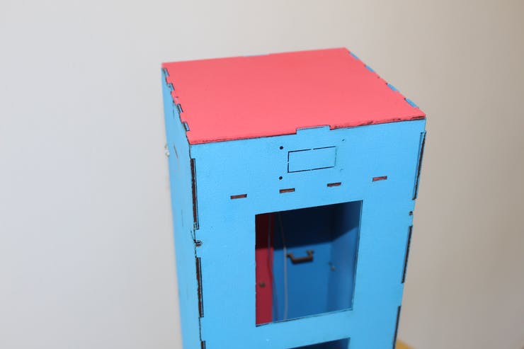
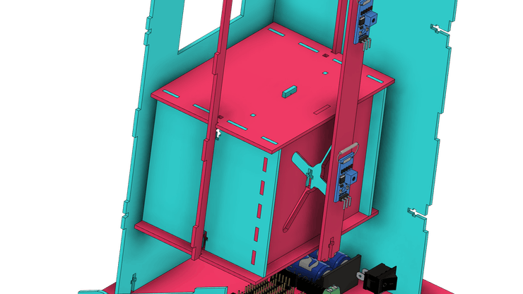
The figure below shows the complete structure of the project. The elevator consists of 4 floors and a control interface
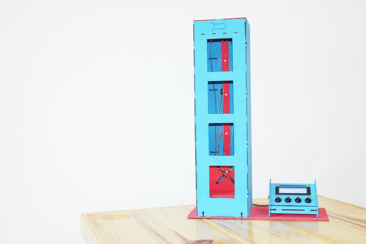

The control interface consists of 4 buttons and a 20x4 LCD. The user will be able to control the elevator positions from each button and will receive system information on the structure's display.
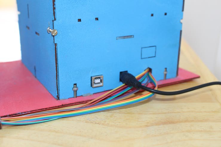
The control box is connected to the rear of the elevator.
The control box is connected to the rear of the elevator. See the figure below.

The wires enter this back region and connect with the Arduino, which is responsible for processing the programming logic.
In addition, the elevator structure was created to facilitate its programming and allow the user not to remove the Arduino during the programming process.
Below we have the image of the Arduino in the elevator structure. As you can see, there is an access for the Arduino's USB port and Jack connector for power supply.

All electronics connect to the Arduino through the use of this shield. The shield is shown in the figure below.
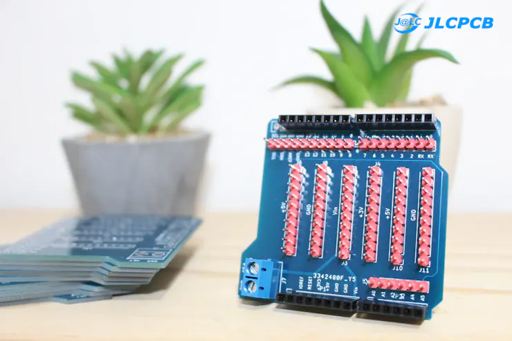
Shield can facilitate the assembly process for your entire project. Find out why!
Why use the Shield on Arduino UNO
There are 2 big problems that will arise if you don't use the shield in your project: faulty connections with solders and the absence of power terminals for sensors and other devices.
Let's understand how to solve these 2 problems?
Look, for example, at the project's sensors. We have 4 sensors to detect the elevator's position. See the figure below.
In total, there are 4 GND's and 4 wires for a +5V connection. Unfortunately, we know that Arduino has only 2 GND terminals and 1 connection pin with +5V.
This forces us to solder these wires together and connect to these terminals.
However, in some situations, solder connection problems arose, and the devices did not work correctly in the project. This takes time and keeps you from moving forward.
To prevent this problem and expand the power pins to make it easier to connect all devices, we created the Shield for the Arduino UNO.

You can apply it to any project with Arduino UNO.
It is available for download,and you can earn 5 units for free at JLCPCB.Follow the step by step and get the shield right now in your home! It's free!
You must follow all these steps below.
- Download the robot control board file
- Enter on this website and make your account.
- Add the control board files to the website
- Add the JLC-REBE discount coupon to the payment section
- Ready, you won 5 free PCB units.
Watch the video below and learn the complete walkthrough
Next, we'll find out which electronic devices in the project will connect to the Arduino's Shield circuit board.
Connection of project electronic devices with Shield Arduino
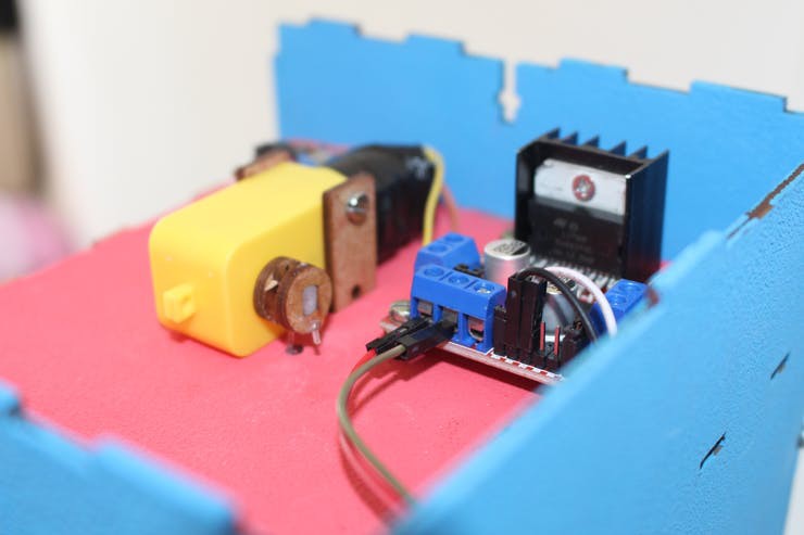
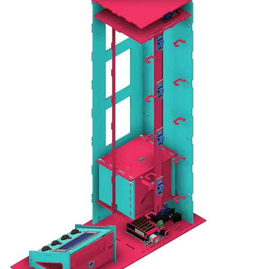
The project consists of several electronic devices. Among them, we highlight the L293D driver and the DC Motor.
L293D Driver and Direct Current Motor
Arduino will send commands to activate the L293D driver and turn the DC motor to move the elevator case.


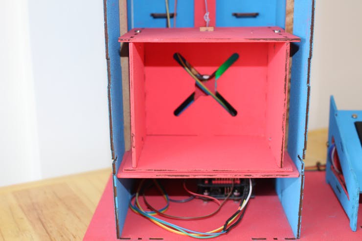
We will place a nylon line on the motor shaft and elevator case to allow traction.
During rotation, the line will be wound on the motor shaft frame. See the figure below.

With that we have the elevator movement up and down. However, we have a problem: how will we know if the elevator has reached every position on the 4 floors?
That's why we should use reed switch sensors. They will allow us to detect the position of the elevator as it moves.
Reed Switch Sensors to Detect Elevator Position
In the figure below we have the presentation of the 4 reed switch sensors.
They trigger when they detect the presence of a magnetic field in their vicinity and will send a high logic level signal to the Arduino's digital pin.
We will use a magnet attached to the back of the elevator shaft to trigger each sensor as it moves.

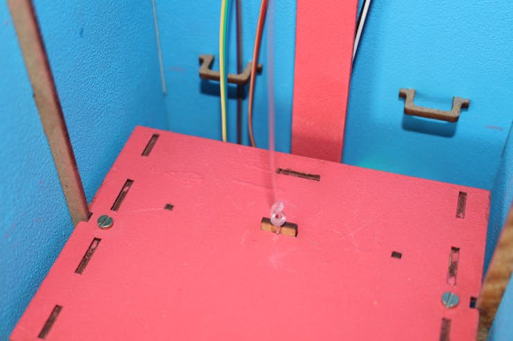
In the figure below, we have the structure of the elevator shaft on the first floor.
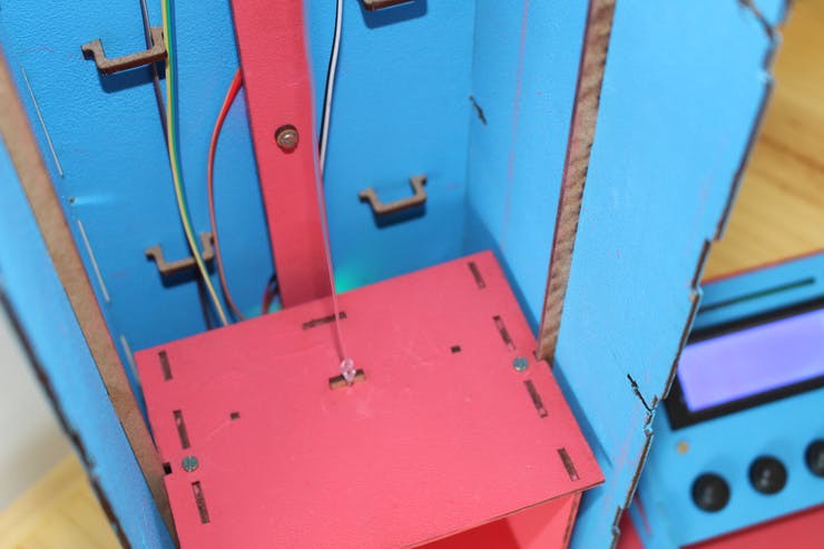
It can be seen that linear guides were implemented in the elevator structure. They are intended to improve the stability of the elevator's movement and to prevent vibrations during its movement.
Consequently, this improves the sensor's detection of the elevator's position.
Below we have another image of the structure of linear guides.

Elevator position is selected by buttons on the project control interface. Next, we will present the structure of the control interface.
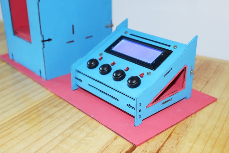
The Arduino Elevator Control Interface
This structure was developed to facilitate elevator control. It consists of a 20x4 LCD and 4 buttons.
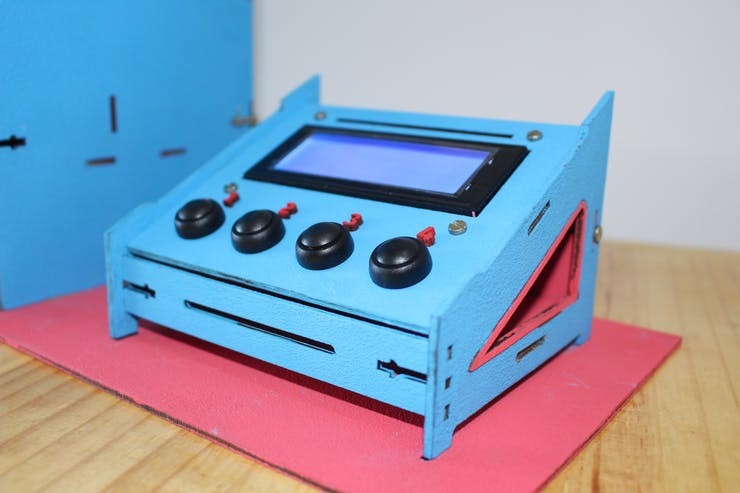
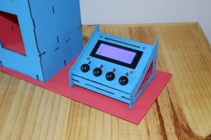
Buttons are used to request the elevator to the desired position.
The LCD is intended to allow the exchange of data between the system and the user. Through it, we will be able to present various information:
- the direction of movement of the elevator
- what position is the elevator
- the floor was requested by the user
- the project's battery level
- and much more.
The LCD used has a SERIAL-I2C converter in order to reduce the number of wires and the complexity of electrical connections with the shield plate.

Now, we'll look at how to create programming logic to control the motion of our JLCPCB Arduino elevator.
The Arduino Elevator Control Logic
Now that you understand how the elevator structure was built, let's understand how to control it with programming logic.
There are several ways to create programming logic to control the movement of an elevator. Our logic will work as shown below.
#include <Wire.h>#include <LiquidCrystal_I2C.h>//Inicializa o display no endereco 0x27LiquidCrystal_I2C lcd(0x27,20,4);//Variavel para controlar a entrada no loopbool controle = 0;bool not_pos = 0;//Variaveis de controle para iteracao nos lacos forint i = 0, j = 0;//Variaveis utilizadas para armazenar a atual posicao do elevador e a posicao desejada pelo usuarioint actual_pos = 0, des_pos = 0;//Vetores para armazenar as posicoes do elevador (sensor) e a posicao desejada pelo usuario (pedido)int sensor[4];int pedido[4];//Inicio da funcao void setupvoid setup(){// Initialization of 20x4 LCDlcd.begin (20,4); //Inicializa o Display de LCD// Initializing the 20x4 LCDlcd.init(); //LCD Backlight Activationlcd.backlight();// Activating the cursor to the 0.0 position of the 20x4 LCDlcd.setCursor(0,0);//Configurando os pinos dos botoes como entrada e pull upfor(int i = 2; i <= 5; i++){ pinMode(i, INPUT_PULLUP);}//Configurando os pinos dos botoes como entrada e pull upfor(int i = 6; i <= 10; i++){ pinMode(i, INPUT);}for(int i = 0; i<4; i++){ pedido[i] = 1;}//Configuracao dos pinos de controle dos motores como saidas digitaispinMode(10, OUTPUT);pinMode(11, OUTPUT);//Comandos para que o motor fique paradodigitalWrite(10, LOW);digitalWrite(11, LOW);}void loop(){//Leitura dos botoes selecionados pelo usuario do elevadorfor(int botao = 2; botao < 6; botao++){ //Armazena o estado de cada botao no vetor pedido pedido[botao-2] = digitalRead(botao); //Verifica qual o andar desejado para o elevador subir if(pedido[botao-2] == 0) { des_pos = botao - 1; controle = 0; } }//Verifica se um dos botoes foi pressionado e se a variavel de controle possui valor igual a 0 if((pedido[0] == 0 || pedido[1] == 0 || pedido[2] == 0 || pedido[3] == 0) && controle == 0){ //Set a value of 1 to the control variable to allow the code stream to enter the condition only once controle = 1; //Execute the loop commands while the control variable is equal to 1 //Reading of all sensors to determine the current position of the elevator for(int sens = 6; sens < 10; sens++) { sensor[sens-6] = digitalRead(sens); } //Comparing the current elevator position with the desired position for(i = 0; i<4; i++) { if(sensor[i] == 1) { break; } } for(j = 0; j<4; j++) { if(pedido[j] == 0) { break; } } if(j == i) { digitalWrite(10, HIGH); digitalWrite(11, HIGH); } if(j < i) { digitalWrite(10, LOW); digitalWrite(11, HIGH); } if(j > i) //2 > 0 { digitalWrite(10, HIGH); digitalWrite(11, LOW); } controle = 0; not_pos = 0;while(not_pos != 1){ //Determinando a posicao atual do elevador for(int sens = 6; sens < 10; sens++) { bool s = digitalRead(sens); if(s == 1) { actual_pos = sens - 5; } } if(actual_pos == des_pos) { digitalWrite(10, HIGH); digitalWrite(11, HIGH); not_pos = 1; for(int i = 0; i<4; i++) { pedido[i] = 1; sensor[i] = 0; } break; }} }}
Next, we'll explain the project's programming logic.
Initially, we inserted the libraries to handle the LCD functions, the I2C communication, and the LCD object was created.
The LCD has been configured for 20x4 with an I2C communication address at 0x27.
#include <Wire.h>#include <LiquidCrystal_I2C.h>//Inicializa o display no endereco 0x27LiquidCrystal_I2C lcd(0x27,20,4);
Declare all variables and vectors used in the project.
//Variable to control loop entrybool controle = 0;bool not_pos = 0;//Variables used to store the current elevator position and the position desired by the userint actual_pos = 0, des_pos = 0;//Vectors to store the elevator positions (sensor) and the position desired by the user (order)int sensor[4];int pedido[4];
After that, we have the setup function. The setup function was performed to initialize the LCD and configure the digital pins as inputs and outputs to control the project's devices.
Among the devices, we have the DC motor, the reed switch sensors, and the control buttons, for example.
//Start of void setup functionvoid setup(){// Initialization of 20x4 LCDlcd.begin (20,4); //Inicializa o Display de LCD// Initializing the 20x4 LCDlcd.init(); //LCD Backlight Activationlcd.backlight();// Activating the cursor to the 0.0 position of the 20x4 LCDlcd.setCursor(0,0);//Configuring button pins as input and pull up for the buttonsfor(int i = 2; i <= 5; i++){ pinMode(i, INPUT_PULLUP);}//Configuring button pins as input for the sensorsfor(int i = 6; i <= 10; i++){ pinMode(i, INPUT);}for(int i = 0; i<4; i++){ pedido[i] = 1;}//Configuration of motor control pins as digital outputspinMode(10, OUTPUT);pinMode(11, OUTPUT);//Commands for the engine to stopdigitalWrite(10, LOW);digitalWrite(11, LOW);}
Now let's discuss the loop function. We implement complete logic for elevator control.
void loop(){//Leitura dos botoes selecionados pelo usuario do elevadorfor(int botao = 2; botao < 6; botao++){ //Armazena o estado de cada botao no vetor pedido pedido[botao-2] = digitalRead(botao); //Verifica qual o andar desejado para o elevador subir if(pedido[botao-2] == 0) { des_pos = botao - 1; controle = 0; } }//Verifica se um dos botoes foi pressionado e se a variavel de controle possui valor igual a 0 if((pedido[0] == 0 || pedido[1] == 0 || pedido[2] == 0 || pedido[3] == 0) && controle == 0){ //Set a value of 1 to the control variable to allow the code stream to enter the condition only once controle = 1; //Reading of all sensors to determine the current position of the elevator for(int sens = 6; sens < 10; sens++) { sensor[sens-6] = digitalRead(sens); } //Comparing the current elevator position with the desired position for(i = 0; i<4; i++) { if(sensor[i] == 1) { break; } } for(j = 0; j<4; j++) { if(pedido[j] == 0) { break; } } if(j == i) { digitalWrite(10, HIGH); digitalWrite(11, HIGH); } if(j < i) { digitalWrite(10, LOW); digitalWrite(11, HIGH); } if(j > i) //2 > 0 { digitalWrite(10, HIGH); digitalWrite(11, LOW); } controle = 0; not_pos = 0; while(not_pos != 1){ //Determinando a posicao atual do elevador for(int sens = 6; sens < 10; sens++) { bool s = digitalRead(sens); if(s == 1) { actual_pos = sens - 5; } } if(actual_pos == des_pos) { digitalWrite(10, HIGH); digitalWrite(11, HIGH); not_pos = 1; for(int i = 0; i<4; i++) { pedido[i] = 1; sensor[i] = 0; } break; }} }}
The first activity is to read the 4 buttons and store their status in the "pedido" vector.
//Leitura dos botoes selecionados pelo usuario do elevadorfor(int botao = 2; botao < 6; botao++){ //Armazena o estado de cada botao no vetor pedido pedido[botao-2] = digitalRead(botao); //Verifica qual o andar desejado para o elevador subir if(pedido[botao-2] == 0) { des_pos = botao - 1; controle = 0; } }
Inside the loop, we check which floor is desired from the pressed button.
//Verifica qual o andar desejado para o elevador subir if(pedido[botao-2] == 0) { des_pos = botao - 1; controle = 0; }
The following condition checks that one of the buttons is pressed and that the control variable is equal to 1.
The "controle" variable is used to allow the condition code to be executed once when one of the buttons is pressed.
The code stream will re-enter this condition when the elevator reaches the position selected by the user.
The following loops are used to read the current elevator position and the floor desired by the user.
//Reading of all sensors to determine the current position of the elevator for(int sens = 6; sens < 10; sens++) { sensor[sens-6] = digitalRead(sens); } //Comparing the current elevator position with the desired position for(i = 0; i<4; i++) { if(sensor[i] == 1) { break; } } for(j = 0; j<4; j++) { if(pedido[j] == 0) { break; } }
These two pieces of information will be used to determine the direction of rotation of the motor to go up or down to the desired floor.
We have 3 conditions. See the code block below. They will be explained below.
if(j == i) { digitalWrite(10, HIGH); digitalWrite(11, HIGH); } if(j < i) { digitalWrite(10, LOW); digitalWrite(11, HIGH); } if(j > i) //2 > 0 { digitalWrite(10, HIGH); digitalWrite(11, LOW); }
When j is equal to i, it means that the elevator is already on the floor requested by the user. In this case, the engine must remain stopped.
When j is less than I it means that the elevator is in a position above requested by the user. In this case, the motor must rotate to lower the elevator.
Finally, we have the last condition, when j is greater than i. In this case, the elevator is in a position below the one requested by the user.
Therefore, the motor must turn so that the elevator can go up.
The next step is to monitor the elevator's position and stop the motor when it reaches the user-selected floor.
This process is done by reading the sensors. See the code block below.
The code will be executed as long as the not_pos variable is different from 1. This variable will change its value from 0 to 1 when the elevator reaches the desired position.
while(not_pos != 1){ //Determining the current elevator position for(int sens = 6; sens < 10; sens++) { bool s = digitalRead(sens); if(s == 1) { actual_pos = sens - 5; } } if(actual_pos == des_pos) { digitalWrite(10, HIGH); digitalWrite(11, HIGH); not_pos = 1; for(int i = 0; i<4; i++) { pedido[i] = 1; sensor[i] = 0; } break; }
The condition below is used to read the current position of the elevator.
//Determining the current elevator position for(int sens = 6; sens < 10; sens++) { bool s = digitalRead(sens); if(s == 1) { actual_pos = sens - 5; } }
Após isso, é feita uma comparação para verificar se o elevador já chegou no andar desejado.
if(actual_pos == des_pos) { digitalWrite(10, HIGH); digitalWrite(11, HIGH); not_pos = 1; for(int i = 0; i<4; i++) { pedido[i] = 1; sensor[i] = 0; } break; }
If true, then the DC motor must to and to out of loop.
After that, it will exit the while, return to the beginning of the void loop function and wait for the user to select a new position.
This is the entire structure designed to control the Arduino elevator.
You can test other logic programming and implement new functionalities in your project.
A GIFT FOR YOU FOR A LIMITED TIME
This printed circuit board is available for download and you can earn 5 units for free at JLCPCB. Follow the step by step and get the shield right now in your home! It's free!
It is available for download,and you can earn 5 units for free at JLCPCB.Follow the step by step and get the shield right now in your home! It's free!
You must follow all these steps below.
- Download the robot control board file
- Enter on this website and make your account.
- Add the control board files to the website
- Add the JLC-REBE discount coupon to the payment section
- Ready, you won 5 free PCB units.
Watch the video below and learn the complete walkthrough.
JLCPCB is a company that is concerned with technological development and is here to support you in the production of your projects.
We appreciate the support of JLCPCB for providing all the support for the production of this project.
Enjoy and get 5 free units for any project with the JLC-REBE coupon.