 Discreet Mayor
Documentation a work in progress!
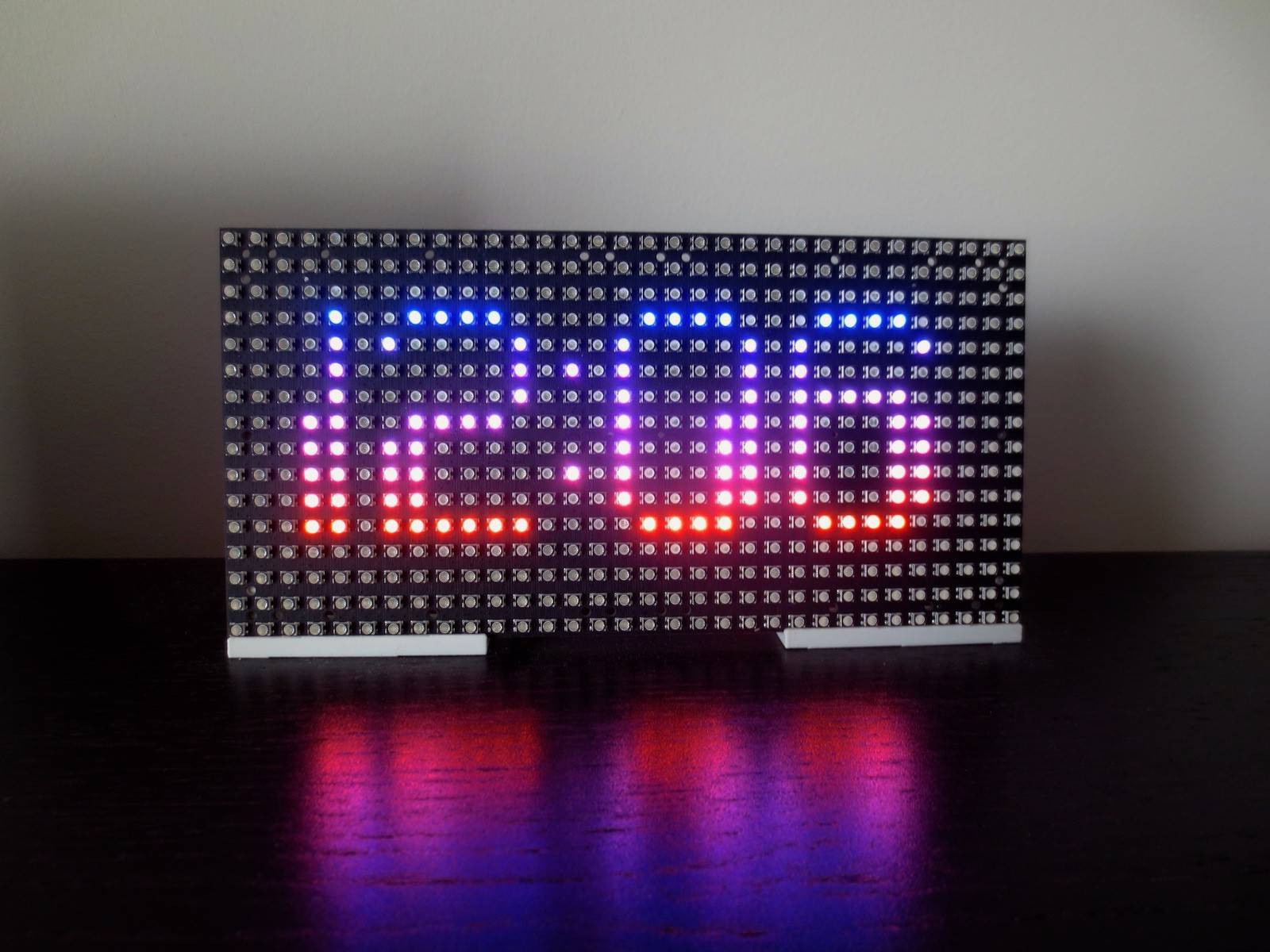
This display is driven by this project, using a simple adapter board for the "75HUB" panels.
Like all other projects here, this automatically associates and joins a private area network using the 802.15.4 protocol.
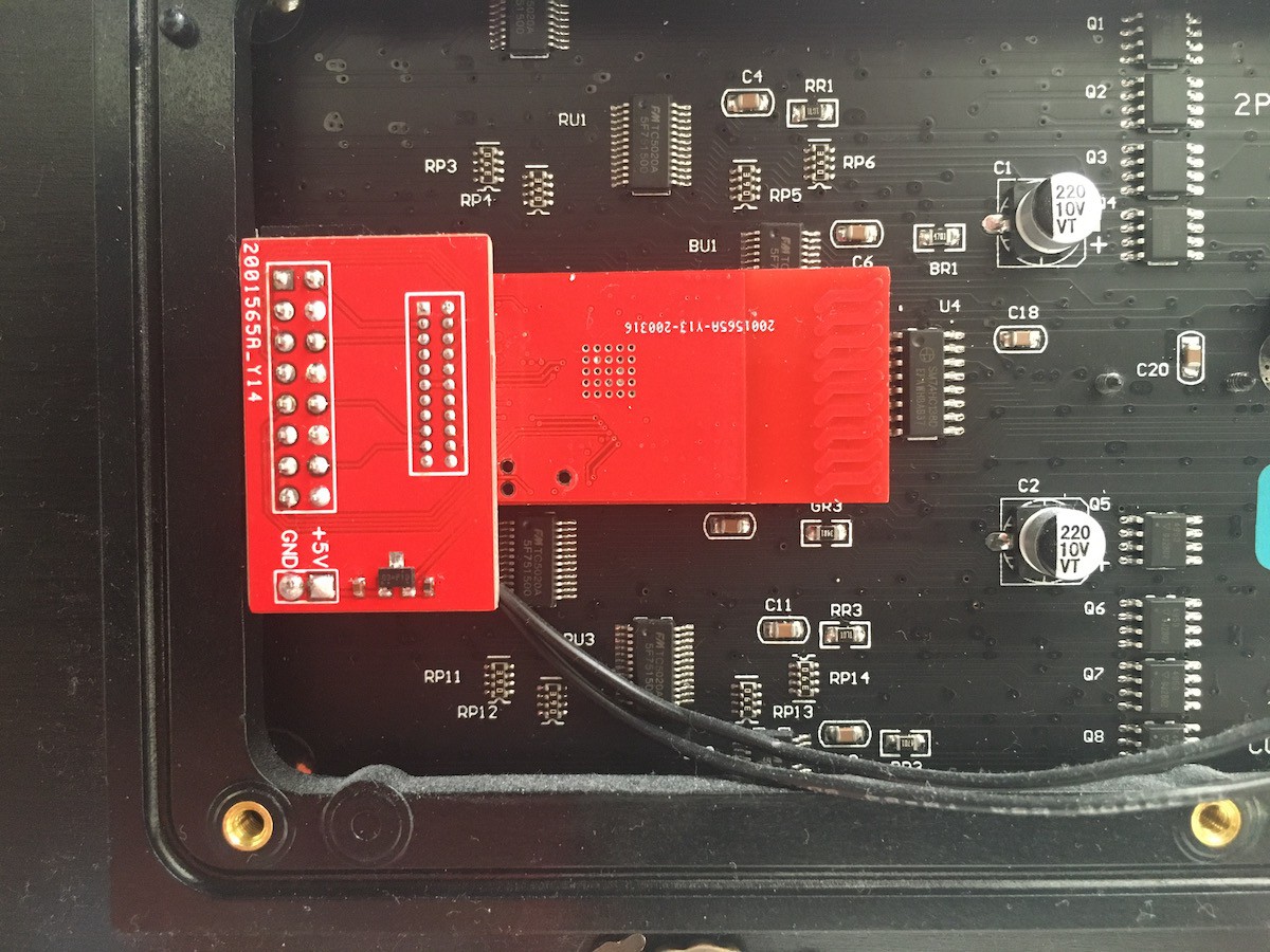
On the back, the adapter board and radio board, driving the panel (and tapping 5V):
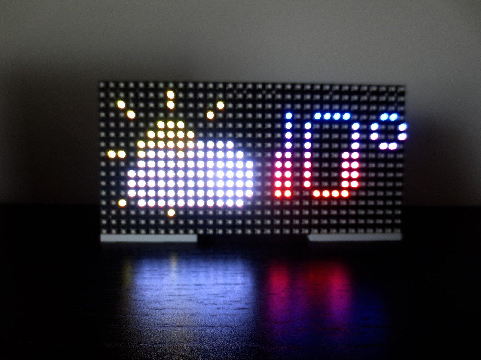
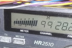
The "base station" (where another one of these connects to a computer through this USB adapter) uses the AccuWeather API to update networked displays every 15 minutes.
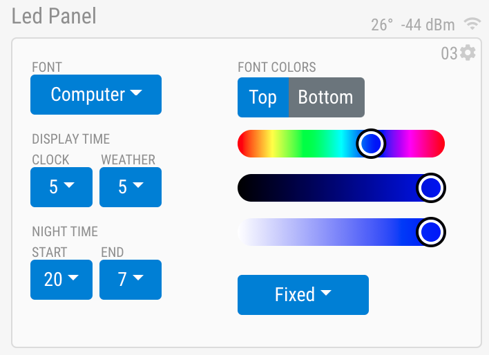
Once on the network, the controls are displayed, where different colours, effects, fonts and timing options can be adjusted.
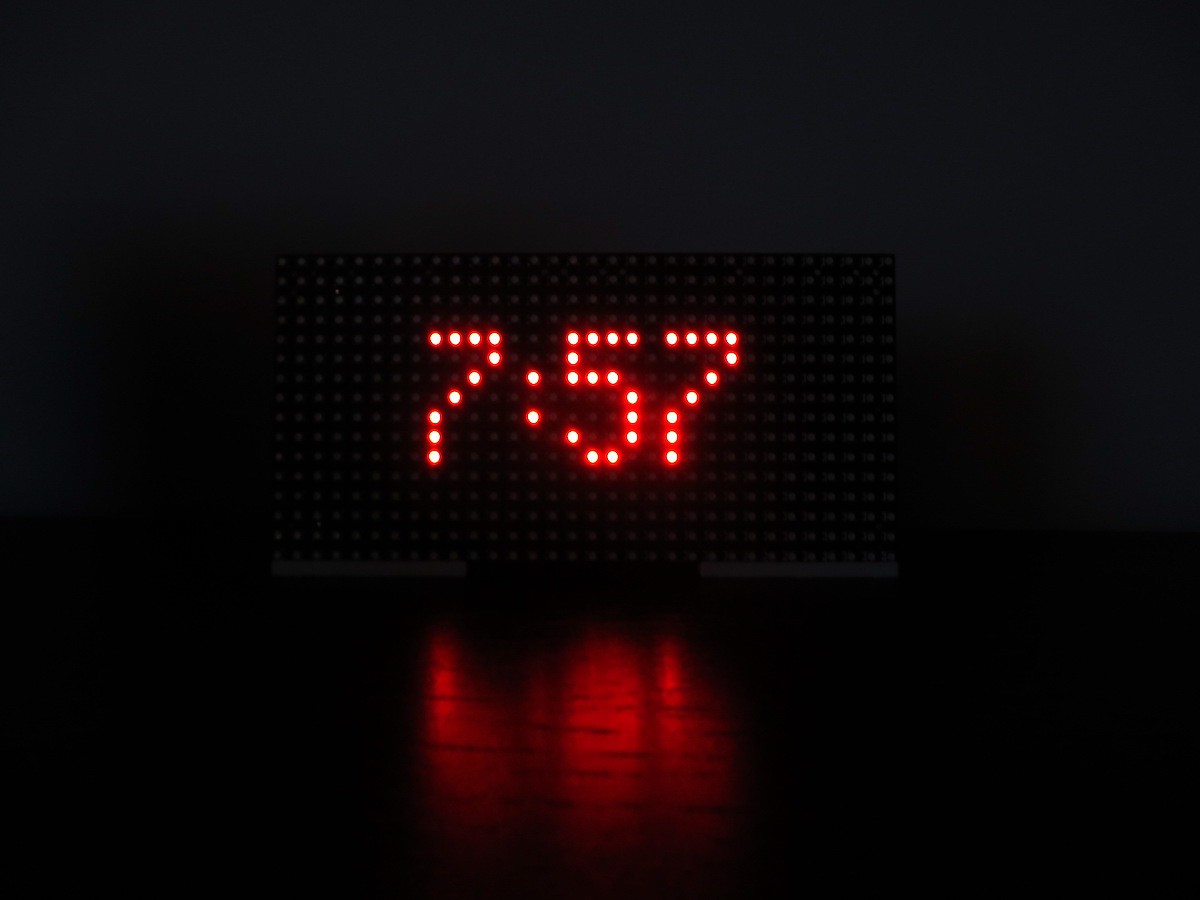
At night, the display switches to nighttime mode until morning. On weekends, nighttime mode is extended a couple of hours.
The firmware uses TI's SensorController core to update the display, so that there is no glitching as other RTOS tasks run (radio, frame buffer changes, etc). The CC13XX family is intended for very different use than this, being low-power devices, and I haven't been able to drive the panels at very high speeds. Using BCM for colour depth, I get 4 bits of precision per channel, and at 5 bits, there is noticeable flicker in darker colours.
One of the fun parts of this project was designing fonts. After looking for a number of solutions, the easiest approach turned out to be to use an online bitmap editor or download any truetype font, and writing my own freetype interpreter, which outputs a struct that's easily used by the firmware:
% ./fontgen ./computer.ttf "0123456789" 16
uint8_t bitmaps[10][16] = {
    {0, 9, 6, 9, 7, 30, 33, 33, 33, 35, 35, 35, 35, 30}, //0
    {0, 9, 2, 9, 3, 1, 1, 1, 1, 3, 3, 3, 3, 3}, //1
    {0, 9, 6, 9, 7, 30, 33, 1, 1, 30, 48, 48, 48, 63}, //2
    {0, 9, 6, 9, 7, 30, 35, 3, 3, 30, 3, 3, 35, 30}, //3
    {0, 9, 6, 9, 7, 32, 32, 34, 34, 63, 6, 6, 6, 6}, //4
    {0, 9, 6, 9, 7, 62, 32, 32, 62, 3, 3, 3, 35, 30}, //5
    {0, 9, 6, 9, 7, 30, 33, 32, 62, 35, 35, 35, 35, 30}, //6
    {0, 9, 5, 9, 6, 30, 1, 1, 1, 3, 3, 3, 3, 3}, //7
    {0, 9, 6, 9, 7, 12, 18, 18, 30, 35, 35, 35, 35, 30}, //8
    {0, 9, 6, 9, 7, 30, 49, 49, 49, 31, 1, 1, 33, 30} //9
};

 ####   #  ####   ####  #      #####   ####  ####    ##    ####
#    #  # #    # #   ## #      #      #    #     #  #  #  ##   #
#    #  #      #     ## #   #  #      #          #  #  #  ##   #
#    #  #      #     ## #   #  #####  #####      #  ####  ##   #
#   ## ##  ####   ####  ######     ## #   ##    ## #   ##  #####
#   ## ## ##         ##    ##      ## #   ##    ## #   ##      #
#   ## ## ##         ##    ##      ## #   ##    ## #   ##      #
#   ## ## ##     #   ##    ##  #   ## #   ##    ## #   ## #    #
 ####  ## ######  ####     ##   ####   ####     ##  ####   ####
Next steps will be to integrate an FPGA (something new to learn) to display 8-bit colour.
 David L Norris
 bornach
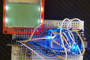
 Nathan Manske
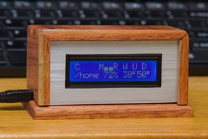
 The Big One