 EK
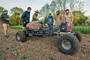
EKLike this on a smaller scale:
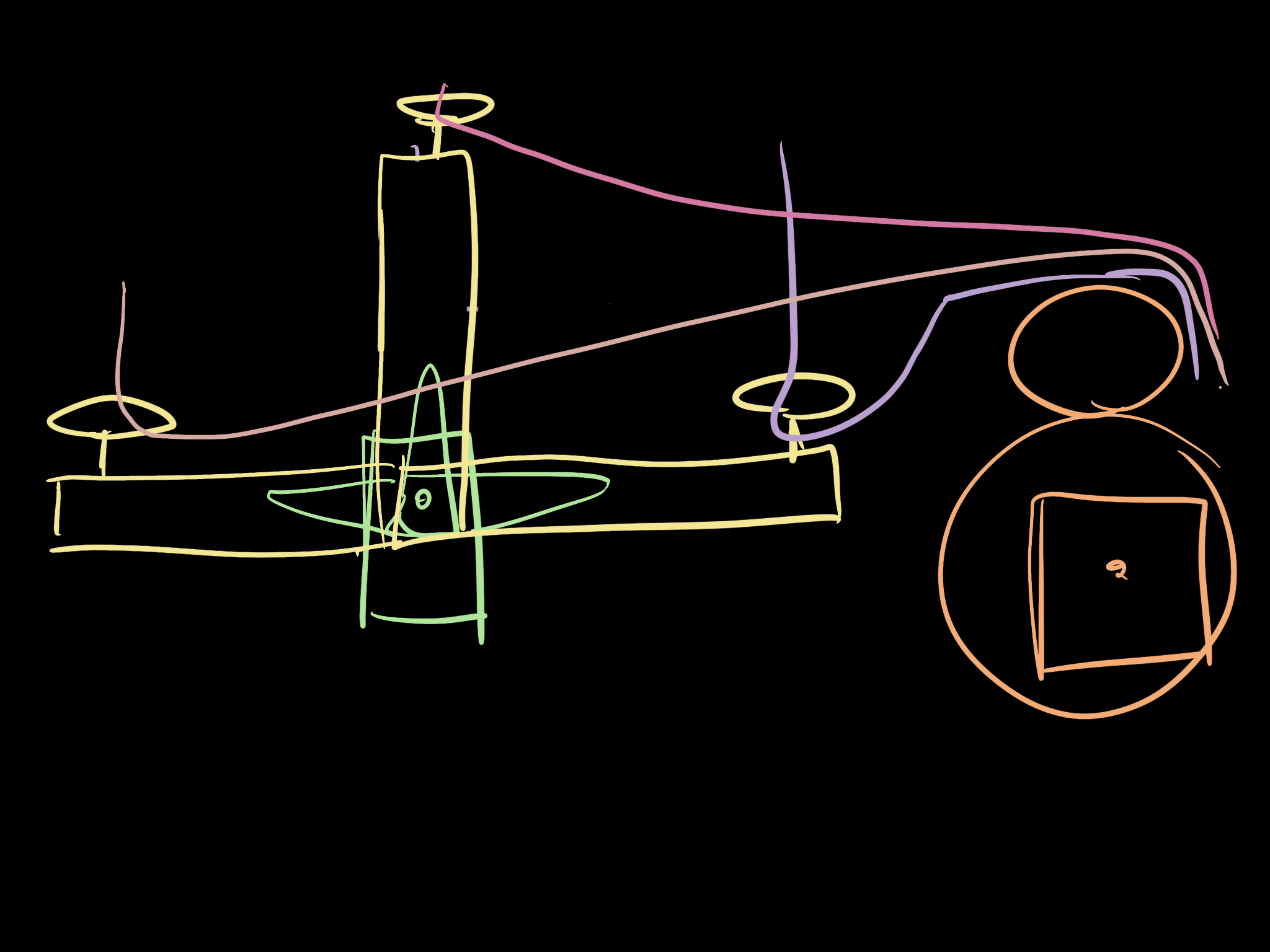
Modifications for this system are:
- Vine can change length (reel in / reel out) via a stepper motor w/encoder
- Point of rotation of the vine is not fixed, this will be attached to a an extended servo arm
- No orangutan
Several applications for space and earth, first this project is focused on the embedded system software.
Requirements
- PWM LED
- Servo motor
- Sensor
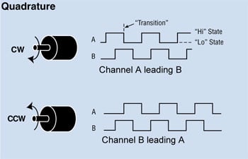
- 2x Hall-effect sensors
- ADC
- Potentiometer for forwards / backwards and speed
- Button that causes an interrupt
- Limit switch for end of reel
- Serial port input and output
- Extra commands and debug info
- Some algorithmic piece incl. a state machine
- Calculate distance travelled based on the encoder
- Hold the position of rope
- Direction of stepping


 Capt. Flatus O'Flaherty ☠
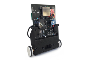
 Ben Steer
 lion mclionhead
 Oskar Weigl
Return to monke!
(Somebody had to say it...)