Close
0%
0%

Custom Fuse Board for MFE21

Making a custom fuse board for a Formula SAE electric car

Similar projects worth following
0 followers
In the context of McGill Formula Electric, we strive to keep our car safe, reliable and performant. Our low-voltage electronics systems are powered by a 24V battery, and to ensure current draws do not exceed the battery and the electrical harness capabilities, we use fuses coupled with a custom fuse board to protect them.

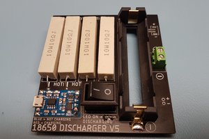
Fuses are ones of the simplest overcurrent protection devices available. When current passing through them becomes higher than a certain threshold, the wires inside the fuse melt and the circuit opens, stopping any extra current from flowing.

In the context of McGill Formula Electric, we strive to keep our car safe, reliable and performant. Our low-voltage electronics systems are powered by a 24V battery, and to ensure current draws do not exceed the battery and the electrical harness capabilities, we use fuses to protect them.

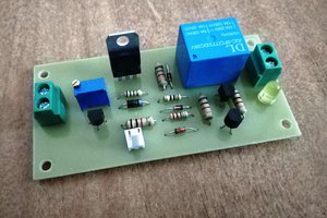
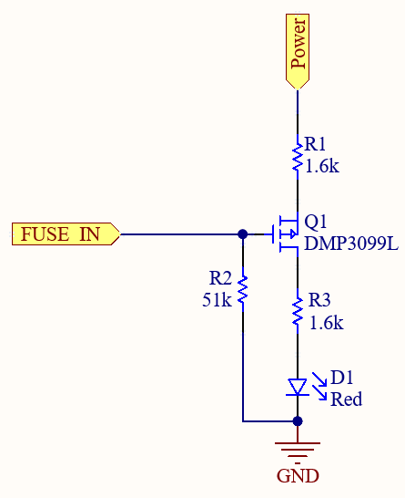
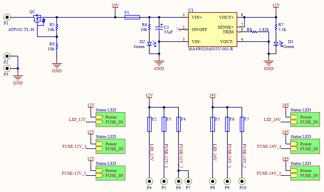
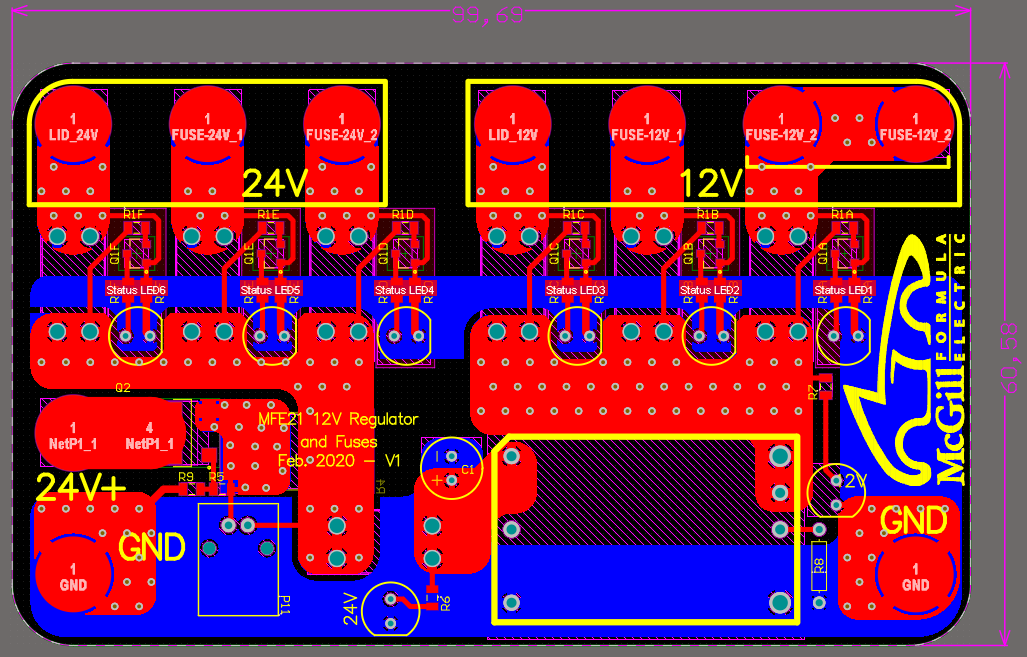
And here comes our custom fuse board. In addition to providing a secure mount for the fuses, it contains an off-the-shelf 250W 24V-12V DCDC converter that is used to power other sensors and data acquisition systems, a PMOS transistor to prevent reverse polarity, and LED indicators that light up when fuses are blown or disconnected. This feature was added to help with debugging and servicing the car.

This article is published in collaboration with JLCPCB. With over a decade of experience in PCB manufacturing, JLCPCB provides some of the highest-quality PCBs available at the lowest-cost.

  • 1
    Schematics

    The first step in making a printed circuit board is to draw the schematics. After choosing the components, the schematics were drawn in Altium Designer.

    As it can be seen in the schematics, Q2 protects against reverse polarity. If the 24V and GND connections coming from the battery are flipped, the PMOS gate voltage is high and current flow is prevented.

    The fuse indicator LEDs are also driven by PMOS transistors. Under normal conditions, both the Power and FUSE_IN voltages are the same (24V or 12V). If a fuse is blown, or if it is not present, then the voltage on the FUSE_IN net gets pulled down by the 51k resistor and current is allowed through the transistor, which results in the LED turning on.


  • 2
    Board Layout

    The second step consists of physically placing the components on the PCB, ensuring the right footprints are being utilized. The main power traces are wide and doubled by using both the top and bottom layers. This reduces the resistance of the traces and facilitates the high-current requirements of the low-voltage system.

  • 3
    Gerber Files

    Once the design of the PCB is done, it is time to generate the files that will be sent to JLCPCB to manufacture it. These files are called Gerber files and they are an industry standard used to describe PCB fabrication data. Each layer of the PCB (copper layers, solder masks, overlays, etc.) corresponds to a single file.

    To make them ready for ordering, combine all files into a single ZIP archive.

View all 4 instructions

Enjoy this project?

Share

Discussions

Similar Projects

Does this project spark your interest?

Become a member to follow this project and never miss any updates