CIRCUIT EXPLANATION
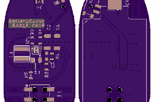
C1 charges through R1 at a rate proportional to the battery voltage. When the voltage across the capacitor reaches the threshold voltage on pin 6 the discharge transistor turns on and discharges C1 through R2. When the voltage across the capacitor has fallen to the trigger voltage on pin 2 the cycle repeats. The zener diode D2 stabilizes the voltage across the internal potential divider and makes the threshold and trigger voltages independent of the battery voltage.
To ensure that the zener diode is biased to its working voltage, a bipolar 555 should be used rather than a low power CMOS one which has much higher resistance values in its internal potential divider.
 Alex
Alex

 Manuel Tosone