The circuit
A PDF with the schematics is added to the project.
Analog
The analog core of the differential probe consists of an instrumentation amplifier in the well-known 3 opamp topology. A voltage divider first attenuates the signal 10 times. To compensate for possible input capacitance, an RC circuit is placed in parallel with the input resistor. Also, a trimmer capacitor is placed over the input to ground to reduce ringing. ESD-protection diodes are placed over the inputs. The signal is then fed into an ADA4817-2. This opamp has a typical input bias current of only 2 picoamperes, minimalizing its effect on the voltage divider. The third opamp is an LTC6228. This fast and high slew-rate amplifier should be well-capable of driving the cable. A gain resistor for the in-amp can optionally be fitted. So far, a gain of one has been used. Also, the DC offset of the circuit can be adjusted. The opamps are supplied with a +/-5VDC supply.
Power supply and management
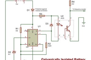
The circuit is powered by a 1 cell 270mAh LiPo battery. An SY6926 battery management IC is used to charge and discharge the battery. This circuit also contains a step-up converter, which creates a voltage of 5.5V. A switched capacitor inverter is used to get a -5.5V rail. The two 'noisy' rails are fed into an LT3032 positive and negative LDO. This double LDO then creates both the positive and negative 5V power rail.
It is obviously important that a battery powered circuit can be turned off, and that it consumes as little as possible power in the off-state. According to the datasheet, the SY6926 still draws 10uA from the battery when the IC is disabled. To reduce the off-state current, off course ideally a more suitable battery management ic should be used. The SY6926 was chosen because it was available, thus instead an extra circuit for reducing the battery leakage was added. A P-mosfet is added in series with the battery at the high side. The mosfet's gate is pulled up by the battery voltage. Only when the gate is pulled low by either the power switch being in the on-position, or a charger being connected, the mosfet will conduct. A second P-mosfet in reverse direction is neccessary to block currents from going through the drain-source diode. When the circuit is turned off, the leakage current consists of the reverse leakage through diode D6, leakage from collector to emitter in Q1, and leakages through the clamping diode of Q3. Given that Q1 is fully turned off, these should be really low in the nano ampere range.
Another important feature of a battery powered circuit is a battery indicator. A simple circuit using 2 comparators is used to compare the battery voltage to a certain reference. This reference does not need to be very precise because when a LiPo is almost discharged, the voltage starts to drop quiet rapidly. The threshold is set by a simple voltage divider and using the 5.5V output of the SY6926. When the battery voltage comes under the set threshold, an LED starts flashing.
Test and measurement results
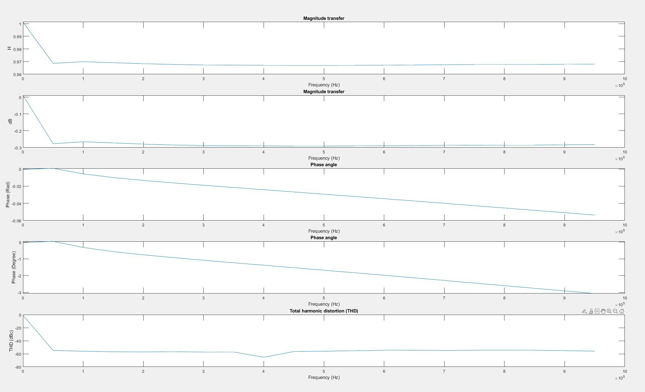
Frequency analysis measurements performed using a Rigol DS1054Z oscilloscope and Feeltech FY6900 signal generator, using a MATLAB script that can be found here. In the first plot, a frequency sweep from 1- 950KHz is performed, with intervals of 50KHz.
Possible improvements
Allthough the core of the probe of the first version works fine, there are a few mistakes. First of all, the status LED is pulled up to the USB voltage, meaning the status LED's only work when a usb cable is connected. It also turned out that the BUS-pin of the SY6926 needed more capacitance then the 20uF provided to be able to start the step-up converter and stabilise. Finally, the battery voltage was directly connected to the input of the comparator for measuring the battery status. Instead of the raw battery voltage, the BAT-pin on the other side of the two P-mosfets should be used. This reduces the battery leakage current in the off-state, and probably more importantly:...
Read more »
 George
 Domenic Rodriguez
 ROFLhoff