0%
0%
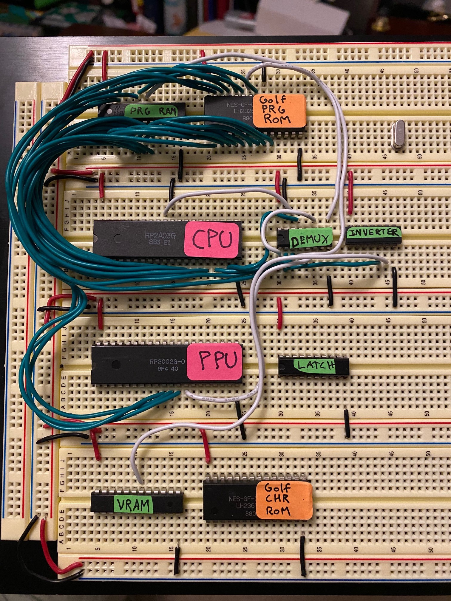
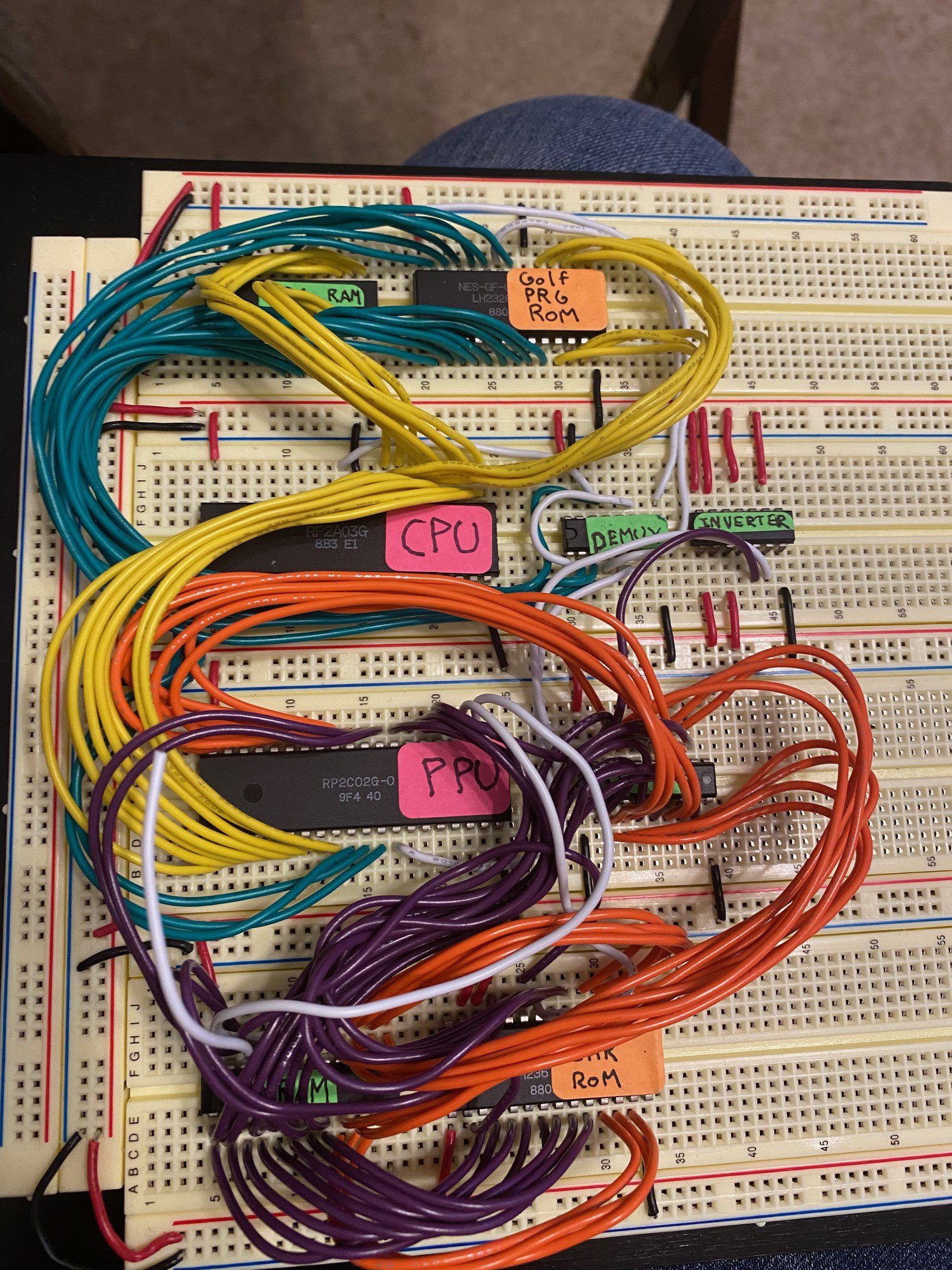
NES Motherboard
Motherboard schematic for the original
Nintendo Entertainment System
 Jesse Robinson (beacon)
Become a Hackaday.io member
Already have an account? Log in.
Just one more thing
To make the experience fit your profile, pick a username and tell us what interests you.
Pick an awesome username
hackaday.io/
Your profile's URL: hackaday.io/username. Max 25 alphanumeric characters.
Pick a few interests
Projects that share your interests
People that share your interests


 Martin Maly
 Nick Sayer
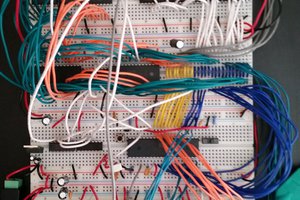
 Nick Bild
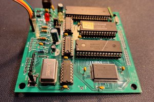
I have some NES related scans here: stripclub.arcade-tv.de