 Shranav Palakurthi
...or a win for hackers?
I'm not sure.
In my pursuit of complete pin-compatibility, I think I found the solution. And guess what? It doesn't need any external components (more on that later).
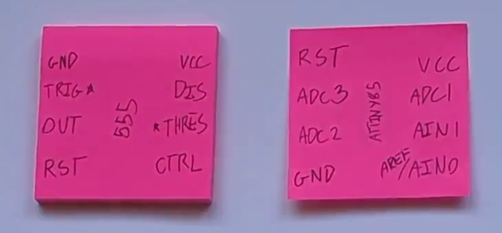
As it is right now, the ATTiny555 is placed in a "standard" orientation, which means that the top of the chip is at the top of where the 555 would have been.
Although everything works as expected, there's still the issue of the ground and reset pins being swapped. Since both of these pins are connected in hardware, there isn't much that we can do about changing it. Although you can reflash the chip to disable the reset, it doesn't do much to help with the pinout issue.
But, what if the chip was flipped and rotated 180 degrees?
Now, the ground and reset pins are aligned.
But what about VCC? It's now where the control pin is. Well, here's the good news: normally, the control pin is isolated from ground via a capacitor. That helps us. All we have to do is bridge PB0 (the top right pin on the flipped/rotated chip) to the VCC pin, and we should be good. Since both the trigger and threshold pins are now aligned with ADC inputs, there's no need for external components! Cool!
I'm going to try this and let you all know how it goes.
Discussions
Become a Hackaday.io Member
Create an account to leave a comment. Already have an account? Log In.